Abstract
Traditional solutions developed for the aerospace industry must overcome challenges posed for automation systems like design, requalification, large manual content, access, and tight tolerances. At the same time, automated systems should avoid the use of dedicated equipment so they can be shared between jigs; moved between floor levels and access either side of the workpiece. This article describes the development of a robotic system for drilling and inspection for small aerostructure manufacturing specifically designed to tackle these requirements. The system comprises three work packages: connection within the digital thread (from concept through to operational metrics including Statistical Process Control), innovative lightweight / low energy drill, and auto tool-change with in-process metrology. The validation tests demonstrating technology readiness level 6 are presented and results are shown and discussed.
Introduction
True Position Robotics has been a pioneer of robotic augmented intelligence for the past 20 years, working closely with manufacturers, integrators, and product suppliers. The motivation for this project was driven by two key metrics
- – Supply a robotic drilling system for less than £500k (customer defined)
- – At an accuracy of +/-0.2 mm 99.7% confidence limit
From a manufacture’s perspective, there is a significant skills shortage preventing increased production volumes, and dedicated automation is too expensive for all but the largest structures. Robotics is seen as a low cost / low risk option, yet “out-of-box” robots do not have aerostructure build capability. Achieving the specified cost and capability will lead to significant adoption of robotics in aerostructure assembly over the next 10 years.
This project is focused on robotic “small-box” aerostructure assembly, with the most challenging process being countersink drilling.
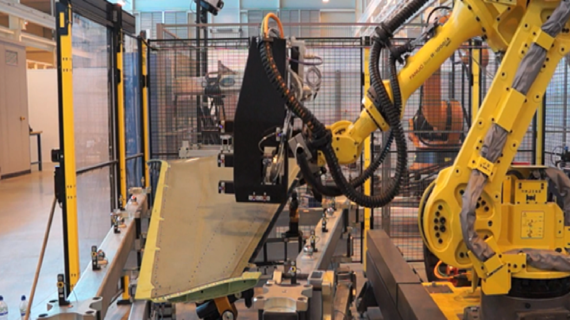
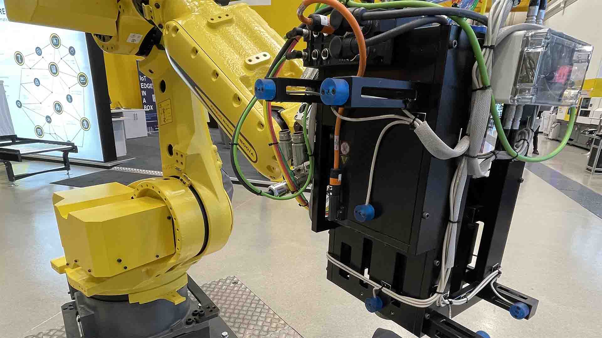
Fig 1.1 Low-cost robot automation in aerostructures
TPR has worked closely with GKN Aerospace over the past 10 years into low-cost aerostructure countersink drilling. Using its augmented intelligence solutions (using large volume metrology), it has managed to decouple Multi-Function End Effectors into simple, lightweight robot tools for drilling, fastening and geometric inspection. Up until that point robots were unable to precisely revisit the same point, with different tools, on different days. Utilising advanced tool change technology, the tools are simplified to 20Kg rather than industry norm of 200Kg+, with lighter robots, half the energy, and significantly a much lower cost.
ADI was the platform to test to TRL 6 TPR’s latest lightweight drill with a new patented clamp-up system, below the customer driven price.
Capability
TPR has supplied services to Airbus for over 20 years in the field of robot capability.
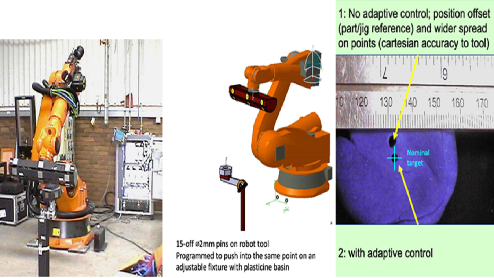
Fig 1.2 Robot calibration (accuracy) and Cell calibration (accuracy)
A quick test was established with TPR at KUKA robotics UK, where a nominal robot program was created to test the concept of metrology guidance. The program was created “off-line” in a robot simulation system. It had a robot-held tool with 15-off 2mm diameter pins – reverse engineered into CAD for precision. The robot program had large joint excitation prior to inserting each of the 15 pins into plasticine, held in a remote cup.
The downloaded robot program was commissioned traditionally by an expert robot engineer – defining the robot “TOOL” and “BASE” using teaching aids, providing a baseline capability.
TPR set-up an alternative solution by instrumenting, defining, and tracking a unique “TOOL” and “BASE” – using a large volume metrology system. This tracked live and simultaneously the 6D Robot “TOOL” and 6D robot “BASE” providing a correction back to the robot – to match the 3D CAD design intent; guiding the robot to the nominal target position defined in the robot simulation relative to the nominal BASE.
The third image in Fig 1.2 shows the crosshair of the demanded target coordinates (central to the cup), and clearly demonstrated the concept of multi-frame robot guidance (product named Adaptive Robot Control, ARC) and was patented.
Switching ARC “off” shows the two key issues of robot capability – clearly seen in the picture where there is a larger hole, offset from the target position. This is what happens in a traditional installation
- The larger hole – caused by machine “accuracy” (how closely it matches nominal machine)
- The offset hole – caused by the definition of TOOL and BASE – cell callibration
These are resolved in production by manual “touch-up” of the robot program – requiring time, creating waste, and spending more money. It also breaks the digital thread, and thereafter production relies on process repeatability.
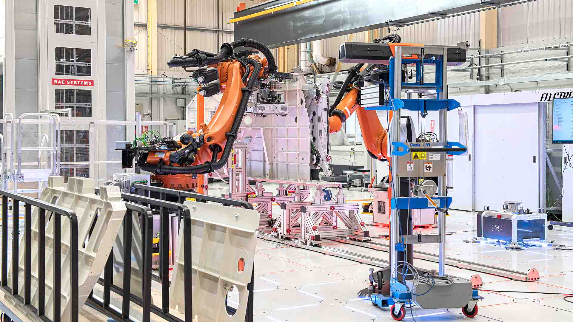
Fig 1.3 Latest multi-camera tracking at BAE Factory of the Future
The work on ARC has continued, including the first realisation in Airbus (now GKN Filton) for leading edge assemblies on A330/A340. Many systems have been deployed over the years through to latest work at BAE in their Factory of the Future.
2.A Digital Thread (DT)
The project goal was to create a full syntax robot program “off-line” [using Siemens’s Process Simulate]. Then provide a robot program to create the countersunk holes, at the desired tolerance, with no manual intervention.
The second stage was to create a separate robot program “off-line” [using Siemens’s Process Simulate]. Then provide a robot program to inspect the assembly and report the results.
2.A.1 Method
The first stage, with all the partners, was to agree a “Statement of Work.” To set the goals of what success looks like
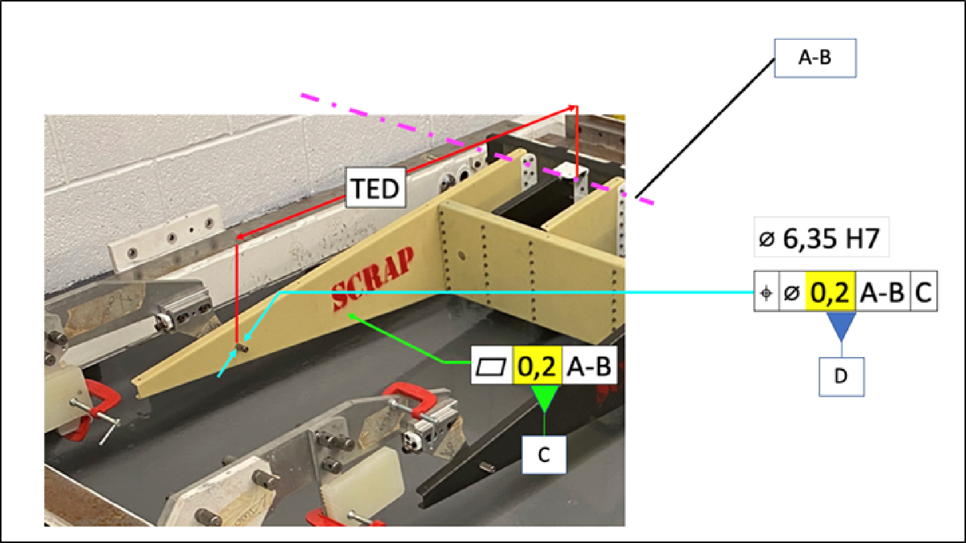
Fig 2.1 Datum structure
The first step (which subsequently proved to be simplistic) was to set a datum system for the assembly. The datum of the fixture is defined by the location of the first rib. The assumption being the jig is fixed where parts are loaded onto a pre-defined tooling pins, to match the spar. It should be noted that this was a section of the full rudder assembly, and the master spar datum hole was not in the section we had, hence using the plane intersect of rib with the master hinge-line datum.
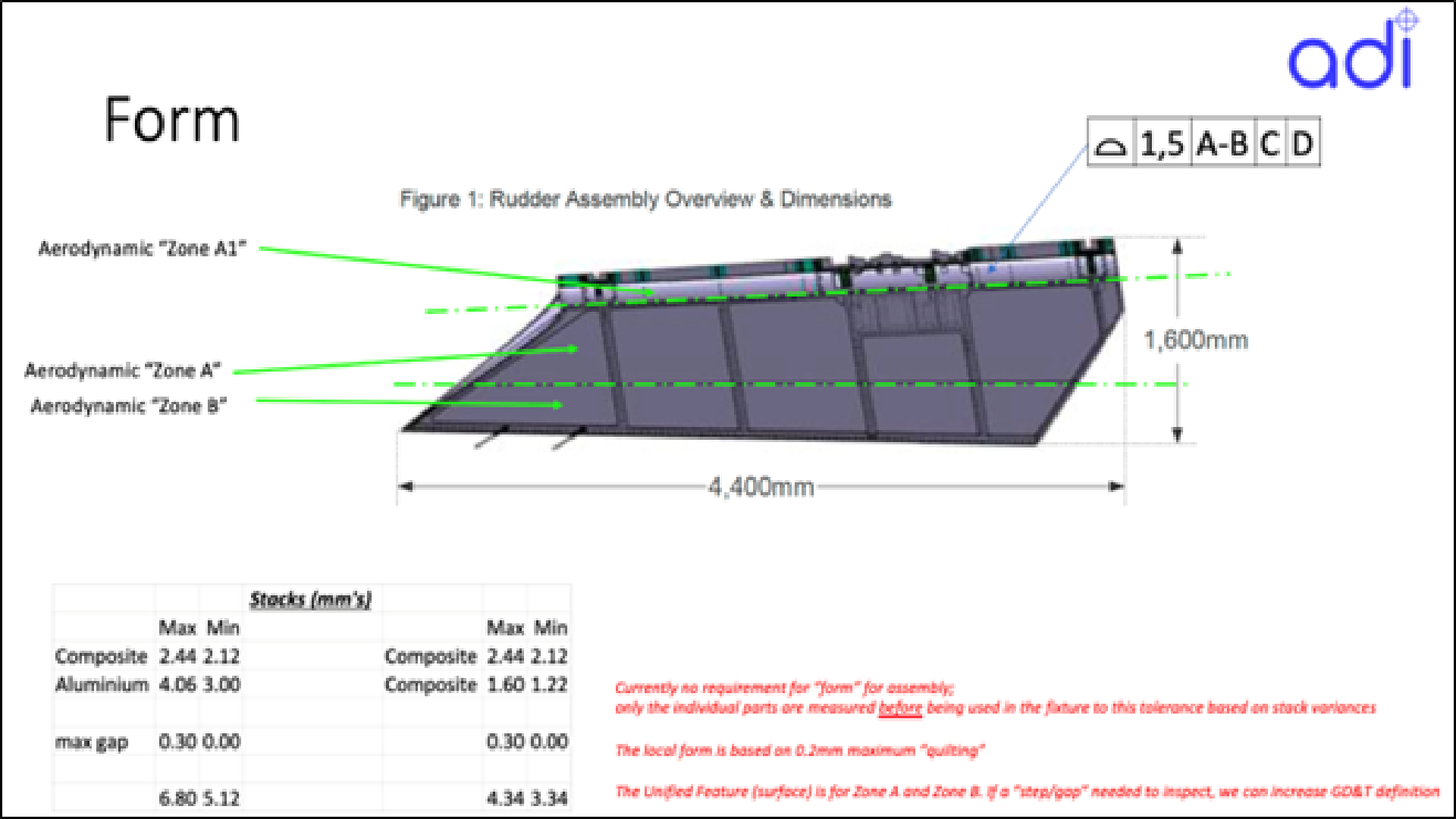
Fig 2.2 Form Control
This set the parameters to measure overall “form”, to be realised with the robotic laser scanner [TPR’s AIR-2 product based on Creaform MetraScan-R, and initially TPR’s AIR-1 based on NDI ProCMM, Nikon’s H120 laser scanner, with TPR scanner housing and metrology integration]
The wide form tolerance is based on the allowable assembly variations, based upon the specified thickness tolerances of composite parts. There is a tighter tolerance for laminar flow over the aerofoil, measured with the same systems.
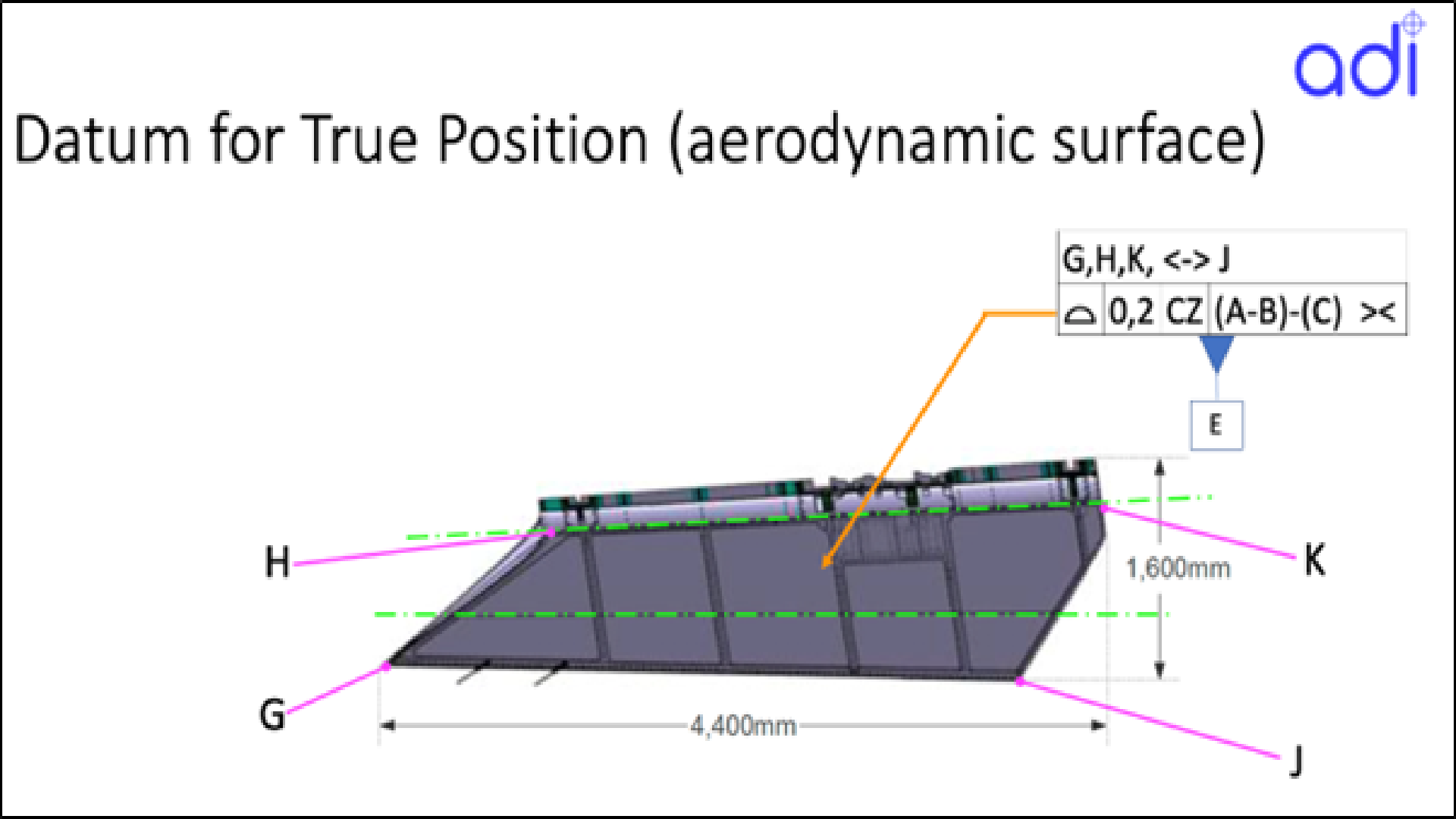
Fig 2.3 Form Control Laminar Flow
The Geometric Dimensioning and Tolerances for the holes was more complicated because the true surface varies build-to-build – based on the thickness of the composite stacks. In this project it was simplified as the holes were applied to a plane, but otherwise they are vectors to intersect onto a nominal point in the master model, and normality referenced to local planes.
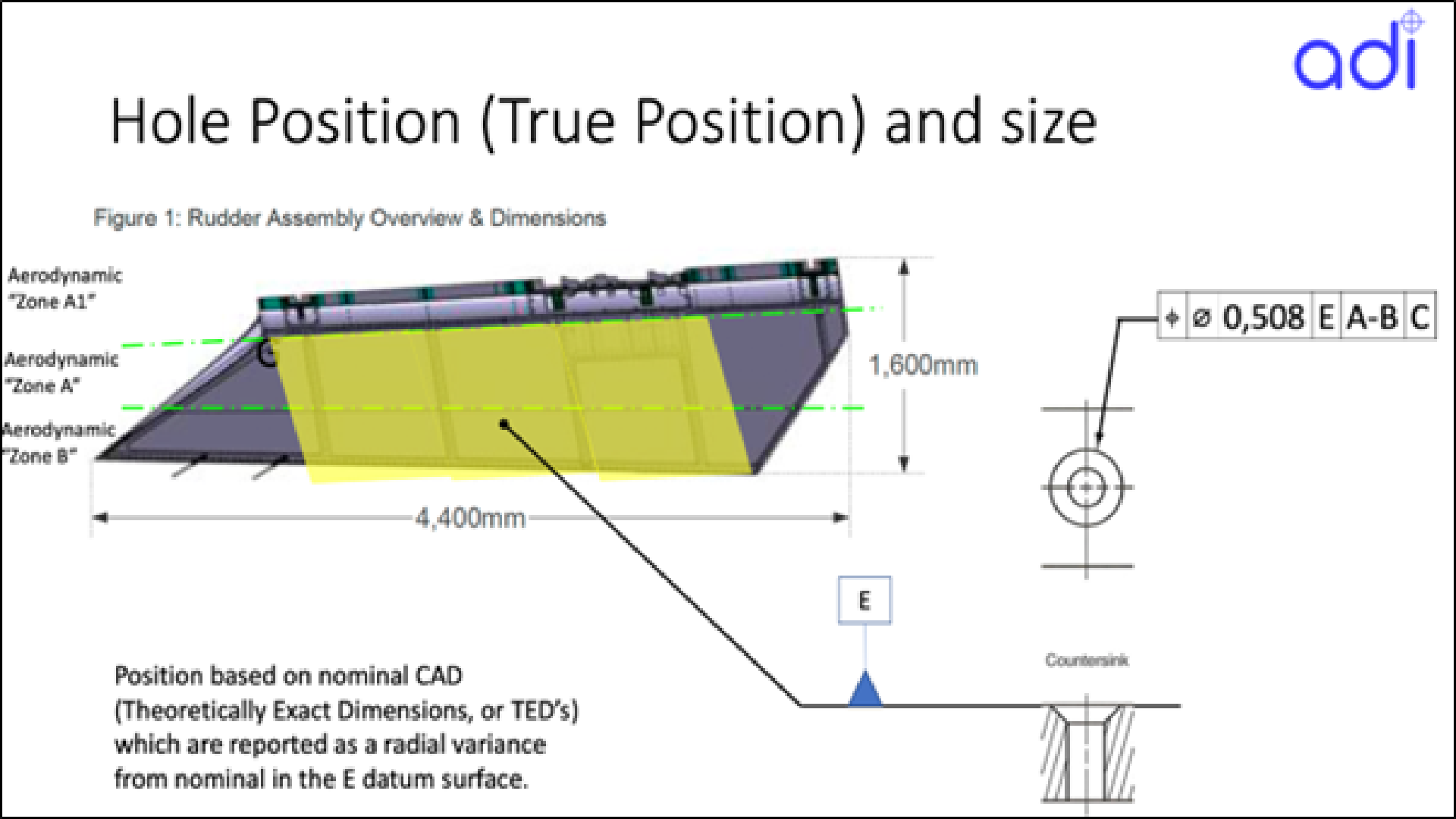
Fig 2.4 Plane for True Position
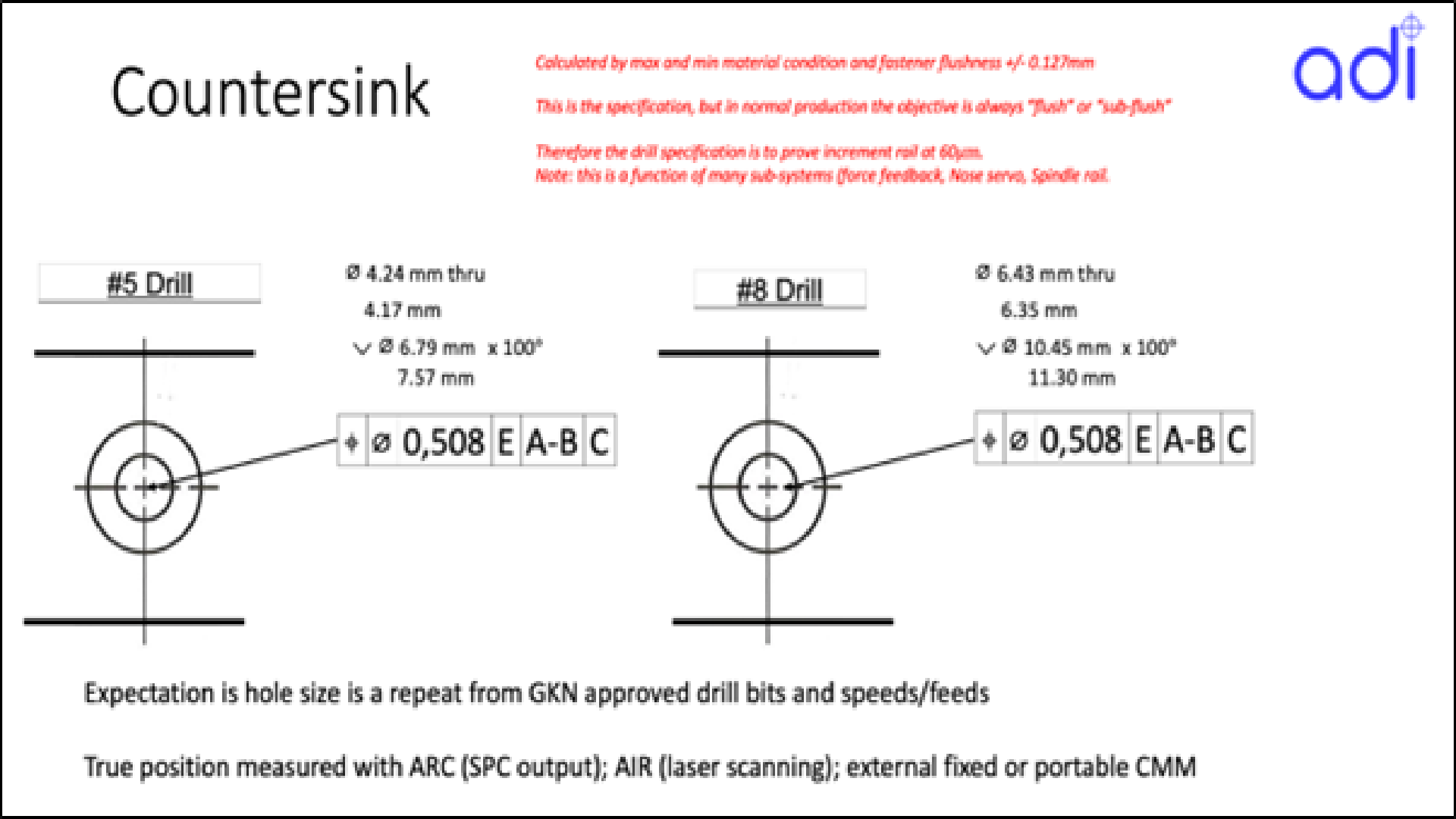
Fig 2.5 True Position requirements
Due to the challenges in scanning resolution (in a large volume) to inspect small countersunk holes, it was decided that the True Position data will be generated from the TPR drill (which is metrology guided artefact in its own right, and acts as a high accuracy 6D touch probe). This concept was tested and matured through TRL4, 5, and 6 gateways – using coupon testing with metrology secondary verification, using Laser Trackers, Laser Scanners and Optical CMM’s.
2.A.2 ADI Project Roadmap
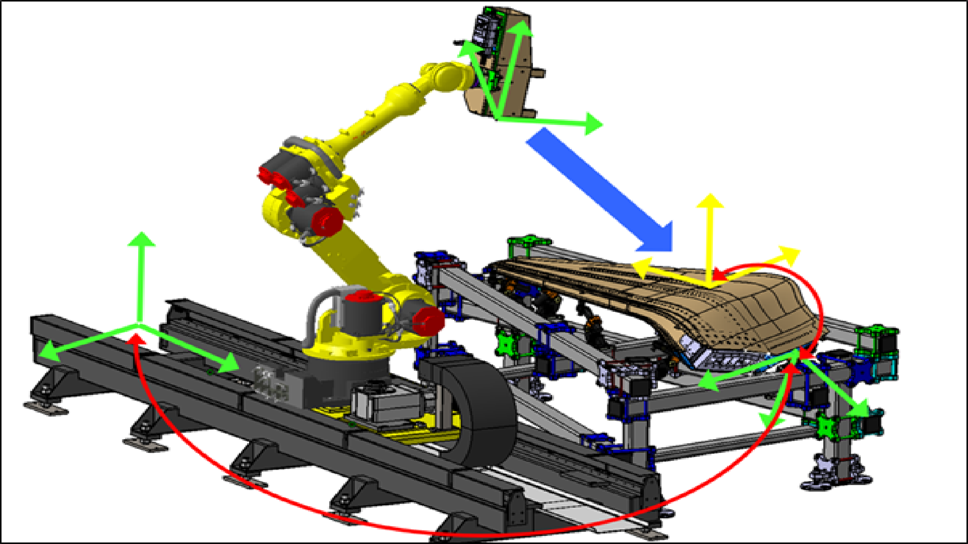
Fig 2.6 Frame Systems in robot simulation
The robot simulation follows the traditional approach of
- – Importing data
- – Assembly (that has its own 6D reference frame)
- – – Fixture (same reference frame)
- – – This defines robot “BASE”
- – Creating target locations on the product – in this case drilled holes
- – Then starting the simulation work
- – – Robot selection
- – – Tool selection
- – – Layout, including part orientation; tool mounting, …
- – – Clash free paths (no tooling liaison here as it was already a completed fixture)
- – – Cycle-time optimisation
- – – Off-line programming
For ADI, there are two use cases – one on discrete points for drilling where the “SPOT” application is used (based on automotive spotwelding). The second is on surface coverage for inspection, where the “PAINT” package was used to ensure all the assembly is scanned.
Advice was sort on how to get the most productive creation of target points. This was based on experience from an older product called RobCAD where target creation was automated by simply creating a window over the area of interest with points and products – and it happened instantly.
There are many happy memories of using RobCAD, but it was a beacon of technology in a sparse manufacturing engineering environment. We escalated our case in Siemens, and they opened our eyes to the full PLM (Product Lifecycle Management) platform. The good news is more engineers have access to more tools than ever, to help them productively do their work. The bad news was the supply chain, supported through Value Added Resellers (VARs) is very vertically integrated – creating several knowledge gaps on how co-workers can actually help one another. The challenge is not so much about “solving problems” in a technology island; but knowing “which questions to ask”. Reaching out to co-workers to maximise your own productivity. With the support of Siemens, several of their VARs, and local InnovMetric master distributor (3D Scanners UK), the early phases of the project (TRL 4 and 5) were performed using several discrete products, all learnt by TPR, and applied to a simple coupon test set-up.
The original starting point was Process Simulate – but that wasn’t the right place!
2.A.3 Mapping the Digital Workflow
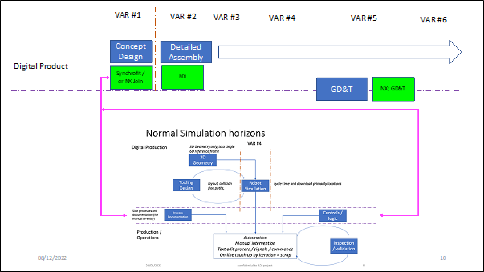
Fig 2.7 Flowcharting digital roadmap
The digital landscape was mapped out using
- – NX Join – to establish full metrics on joining coupons together including features of size on “product”
- – – Input to Process Simulate
- – – Input to drill PLC
- – NX Assembly – To develop datum structures and tooling (Coupon holders)
- – – To manufacture coupon holders
- – NX – GD&T – to tolerance the assembly with respect to tooling
- – NX-PMI+ – to automatically create Polyworks measurement plan (Polyworks Inspect)
- – Process Simulate – Robot Simulation
- – – SPOT for drilling
- – – PAINT for inspection
- – TPR .XML files. These are used to load the right data in the right format into Process Simulate. It’s an open code with templates supplied from Siemens. This was important as the PLM products have different functionality in network and standalone modes. These tools are needed when working remotely from a network.
- – Planned formats for
- – – OLP download
- – – Robot-PLC Coms
- – – PLC recipies
- – – Operations data including inspections
- – – RSH (Robotic Software Hub) – coms format to interface with TPR’s advanced scripting software joining robot, metrology, and analysis software together
- – Polyworks Collaborative Suite (a data loop from shop floor analysis to enterprise dissemination)
2.A.3.1 Concept Design
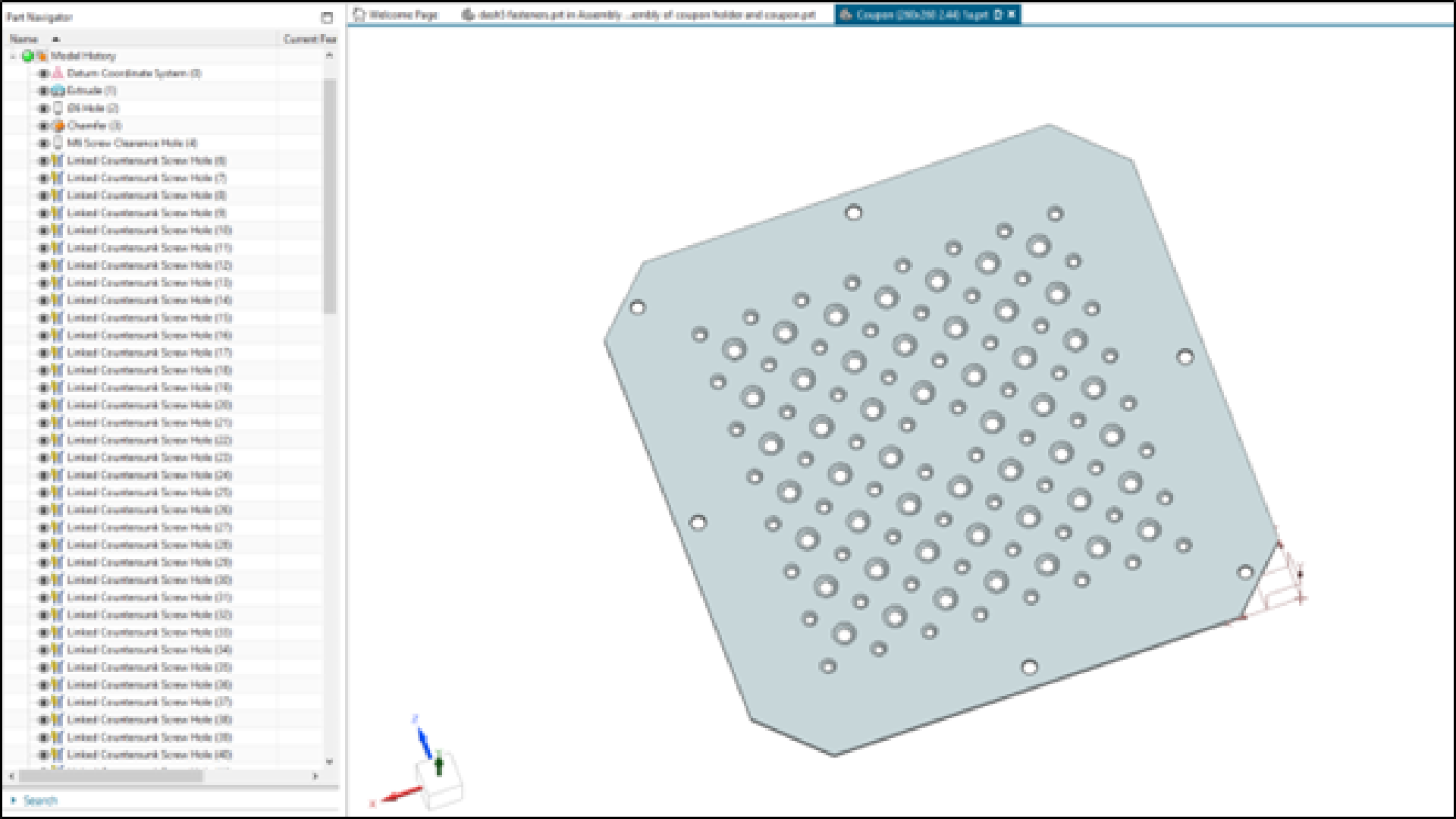
Fig 2.8 Concept design of TRL4 and TRL 5 coupon testing using NX-Join
This is a concept design software with lots of productivity tools. A workflow was demonstrated based on simple coupons – so free to share, without IP limitation. By joining two plates, these tools were used help define features of size and location with respect to the parts being joined.
This product also has smart libraries for drill tools, speeds, feeds etc. So can populate automatically recipies in robot simulation, real robot, and drill PLC.
2.A.3.2 Tooling Design including assembly tolerance in fixture
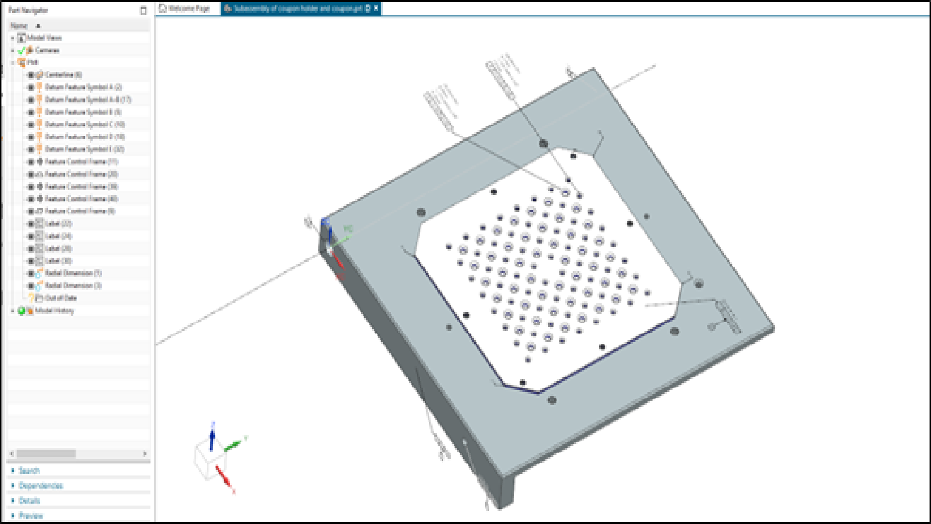
Fig 2.9 Tooling and GD&T of coupon assembly inside fixture for TRL4 and TRL 5
Then another product was used (NX Assembler) here a proper location strategy begins (NX Join doesn’t have a meaningful origin reference). In this package an origin is defined, the tooling created to hold the parts, and then finally an extra module is used – GD&T (Geometric Dimensioning and Tolerancing). This defines the alignment system (to create a measurement reference system) and positional tolerances to the features of size (countersunk holes).
Up to this point the work is primarily for Off-Line robot Programming (OLP) for robot drilling, but this also creates “everything” needed for a measurement plan.
2.A.3.3 Planning inspection strategies
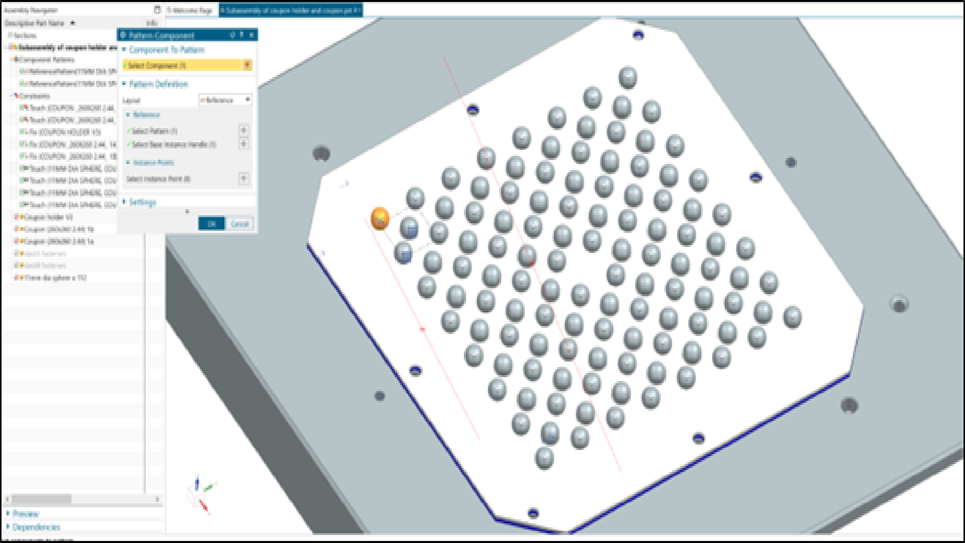
Fig 2.10 Inspection schemes
There were a range of ideas on how to accurately verify / measure the countersink depth. One idea was to place metrology grade tooling balls to sit in each cone. Then in a single laser scanning pass the centres of the tooling balls can be automatically extracted and a height measured with respect to the top surface. This was the method adopted for TRL 4 in addition to independent verification with Laser Tracker – both to correlate with TPR drill.
During the single coupon tests, there were verification issues caused by the manufacturing of the coupon holders. The two holes for concentricity in the jig were manufactured by turning the frame 180° and the planes were not parallel – causing the datum features to not be concentric. This learning was applied to improving the coupons for TRL 5, where there were countersink holes over a much larger volume, and at different angles. The coupon frames were all measured from master datum, then disassembled to take to partner site for independent verification. At this stage there was complete correlation between Laser Tracker, Optical CMM, and Laser Scanner – for confidence in the TRL 6 “in cell” measurements.
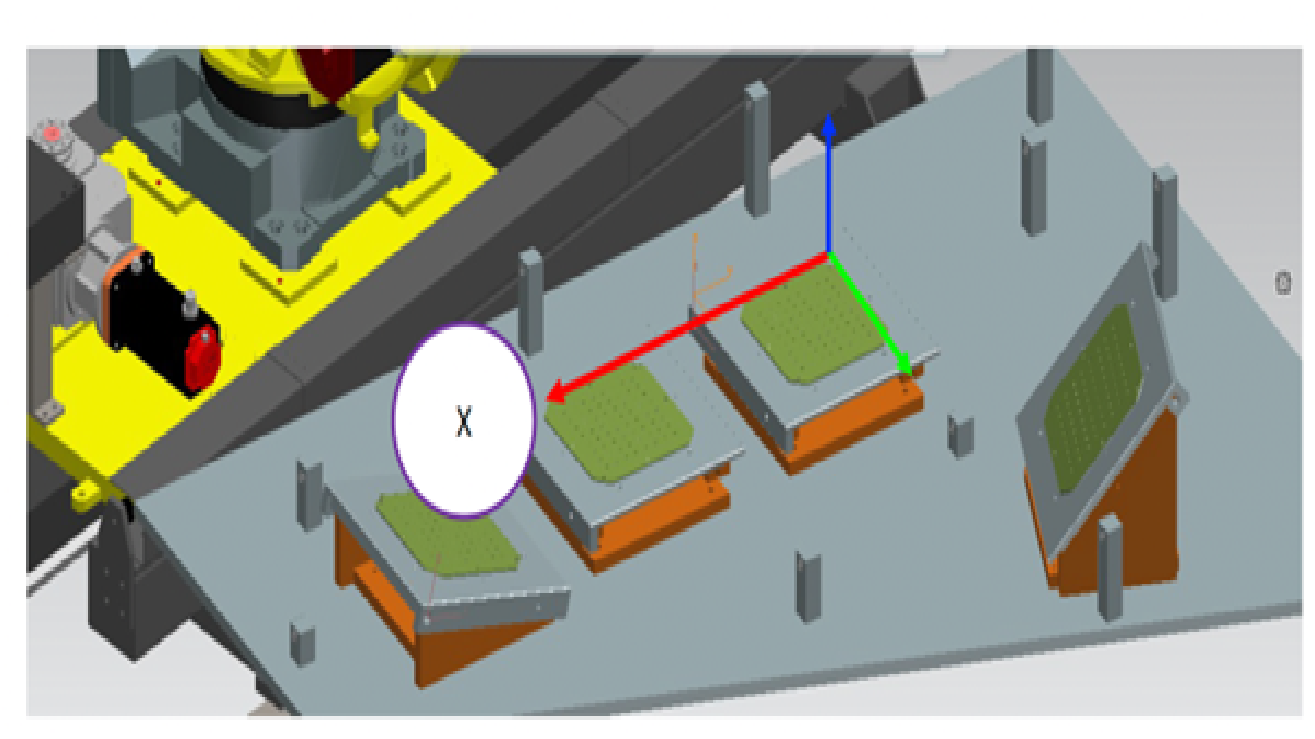
Fig 2.11 TRL 5 configuration.
The Analysis software, Polyworks (from InnovMetric) has a module that sits on the NX Workstation. Literally, with a click of a button the entire Measurement Plan is automatically created. A metrologist or operations team can ask for more items to measure – but there is no “recreation” of measurement features from Excel, pdf’s, … with potential sources of error from manual data input. But it doesn’t end there. On the shop floor, TPR’s Robotic Software Hub is managing all the interactions between metrology, robot, and analysis software (it’s an Open advanced scripting product with standard plug-ins). This is how the management in the robot cell is performed to take measurement plans in, executing robot programs, and exporting results. For InnovMetric, those results go to a local webserver and results populated back into the organisation – not just for Operations, but also the designers, to add corporate knowledge on real capability – that can lead to further savings (such as continuous improvement projects).
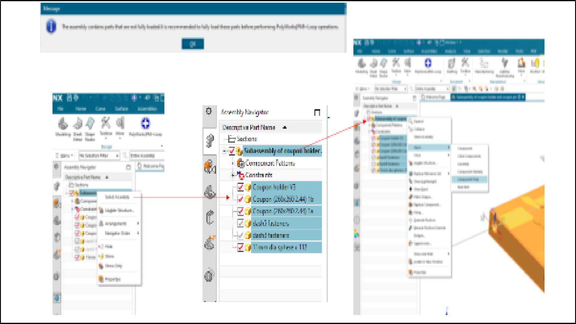
Fig 2.12 Automatic Measurement Plan Creation.
To conclude the testing before moving onto a physical part, TPR’s latest robot guidance (ARC+, Adaptive Robot Control Plus) was tested, and it correctly supplies SPC (Statistical Process Control) data and True Position as planned. This integration uses QC-Calc from ProLink for output back into Digital Thread.
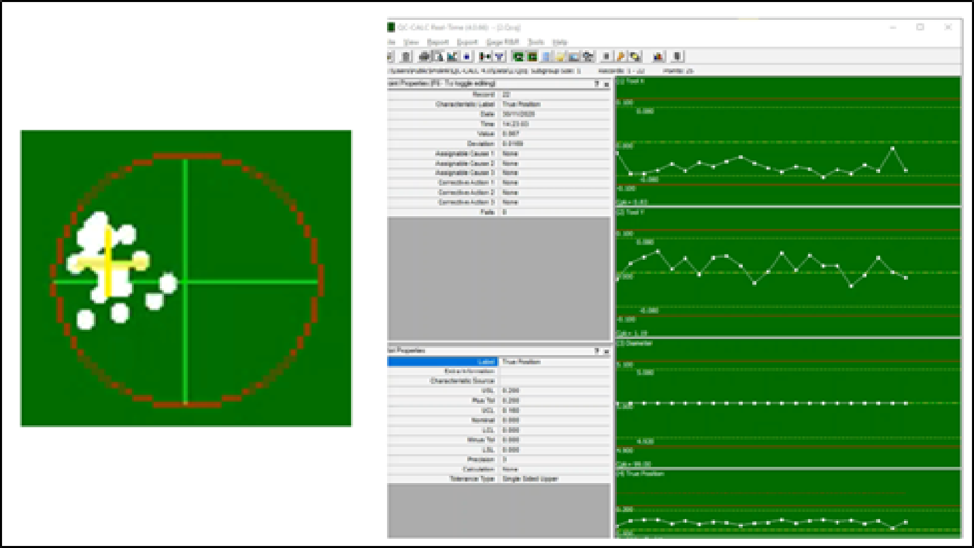
Fig 2.13 TPR’s ARC+ with QC-Calc Integration for True Position and SPC
2.A.3.3 Eureka moment for OLP creation for drilling
Before doing the TRL 6 product OLP’s, discussions were had with the partners. The question posed was, “when is the datum pin D set?” The answer was “Every build.” From an OLP perspective this was a massive moment – probably the key learning from the complete project. The reason for this is to manufacture to a build rule where the OML (Outer Mould Line) of the spar must be flush with the OML of the rib. Based on a +/-5% thickness tolerance the parts can move mm’s within the tooling frame.
Diving deeper into the DT examining the parts – all the holes are dimensioned from the parts. So as the tooling pin moves lower, to meet the flushness criteria – so do all the holes from Skin-Rib. The robot simulation datum frame is not the jig.
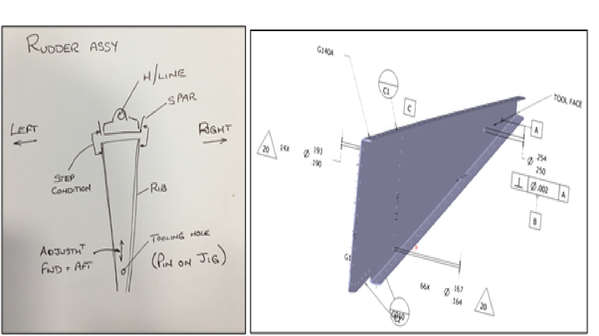
Fig 2.14 Project Eureka moment – the jig is not the robot datum
This was verified by doing a complete robot scan of the sub-assembly in 3D – and checking bracket locations in 1D with a vernier. Where the rib was 5mm from nominal (vertically) and the brackets from the spar were also at a variance from nominal larger than the specified hole tolerance.
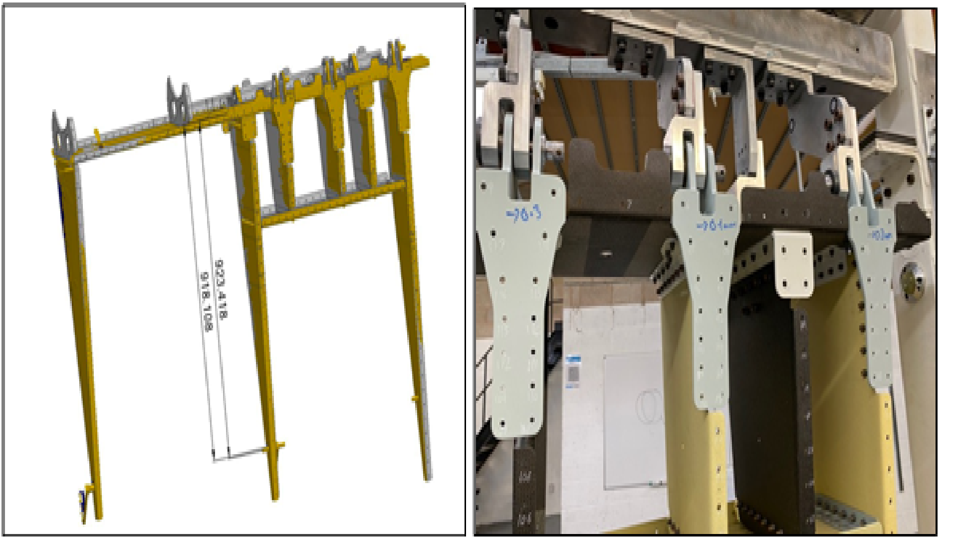
Fig 2.15 Build condition ready to claim skin.
This led a new OLP methodology
- – The design tolerances are respected – namely diametric True Position 0.4 mm (0.2mm radial) as per CAD
- – OLP’s to have a unique BASE reference for each part the tolerances are from
- – Inside the DT all values are nominal
- – However, on the shop floor the positions of those parts need to be updated with regards to their position in the fixture
- – The real robot BASES are automatically updated for that position in the jig
- – But the robot guidance still runs from the CAD origin frames (so the DT is fixed, but the parts can move in the jig based on assembly rules (such as flushness)
- – This was tested by both manual probing and robot scanning
- – The IP added to TPR’s augmented intelligence for the robot
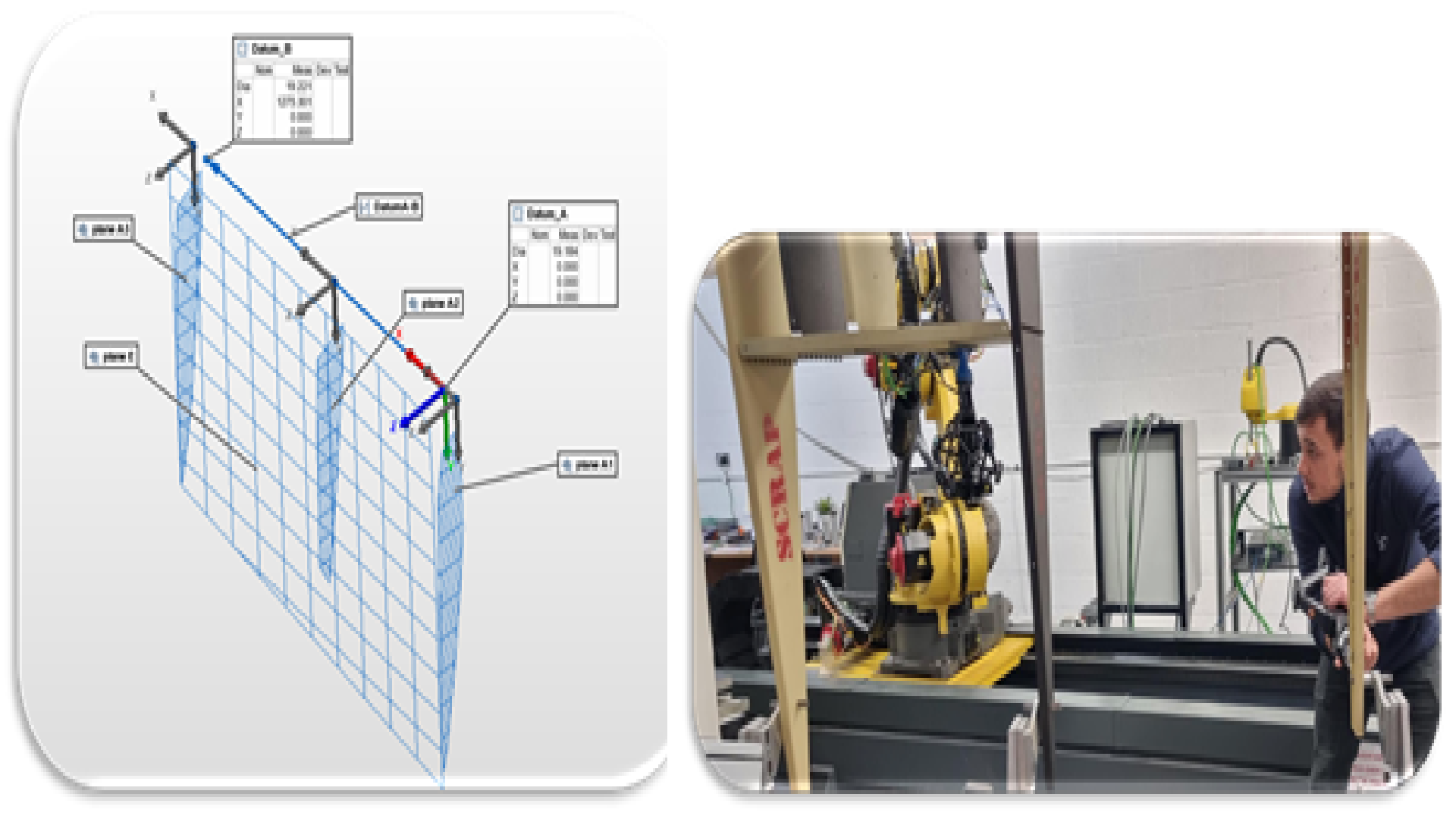
Fig 2.16 Digital Need for multiple reference frames for each part.
2.A.3.4 Data feedback
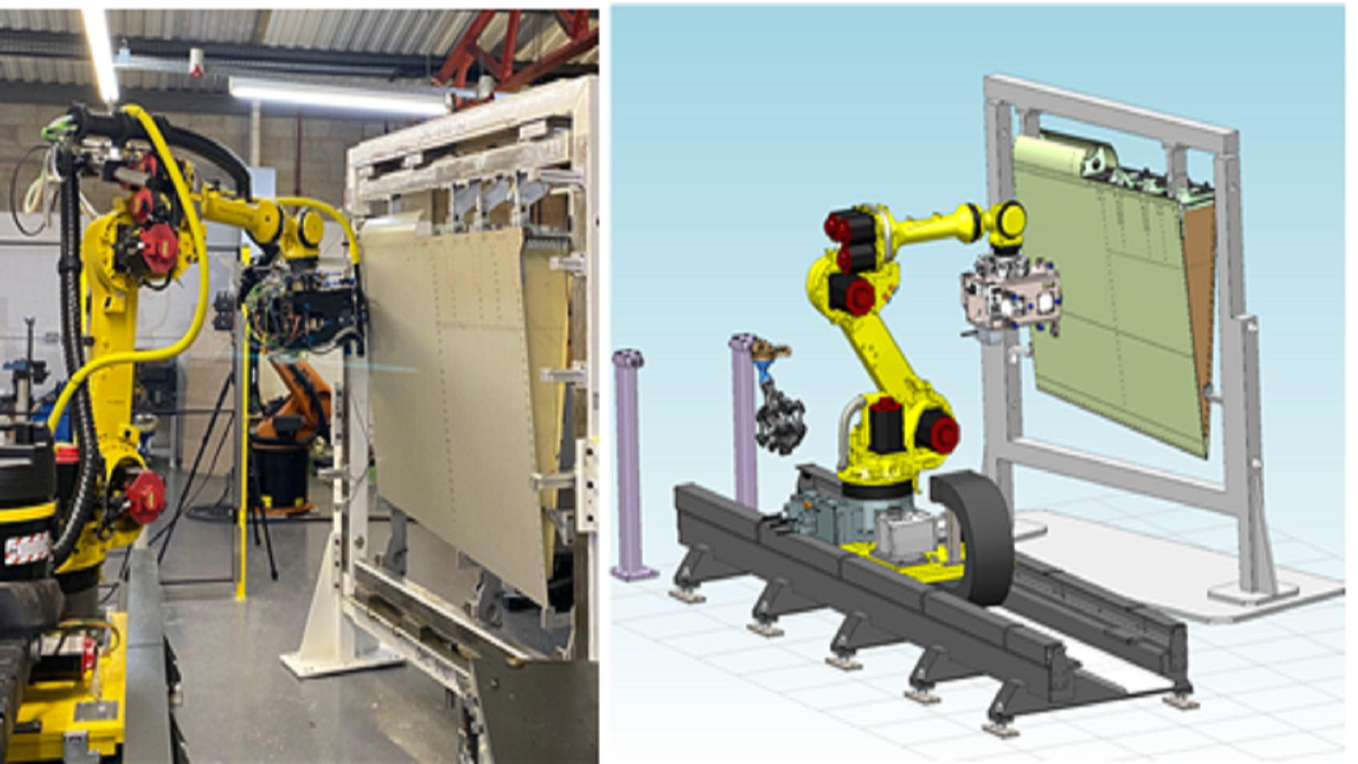
Fig 2.17 Data feedback True Position and Countersink depth
The data from all hole positions and depth was in spec based on new methodology. More details given in the drilling section
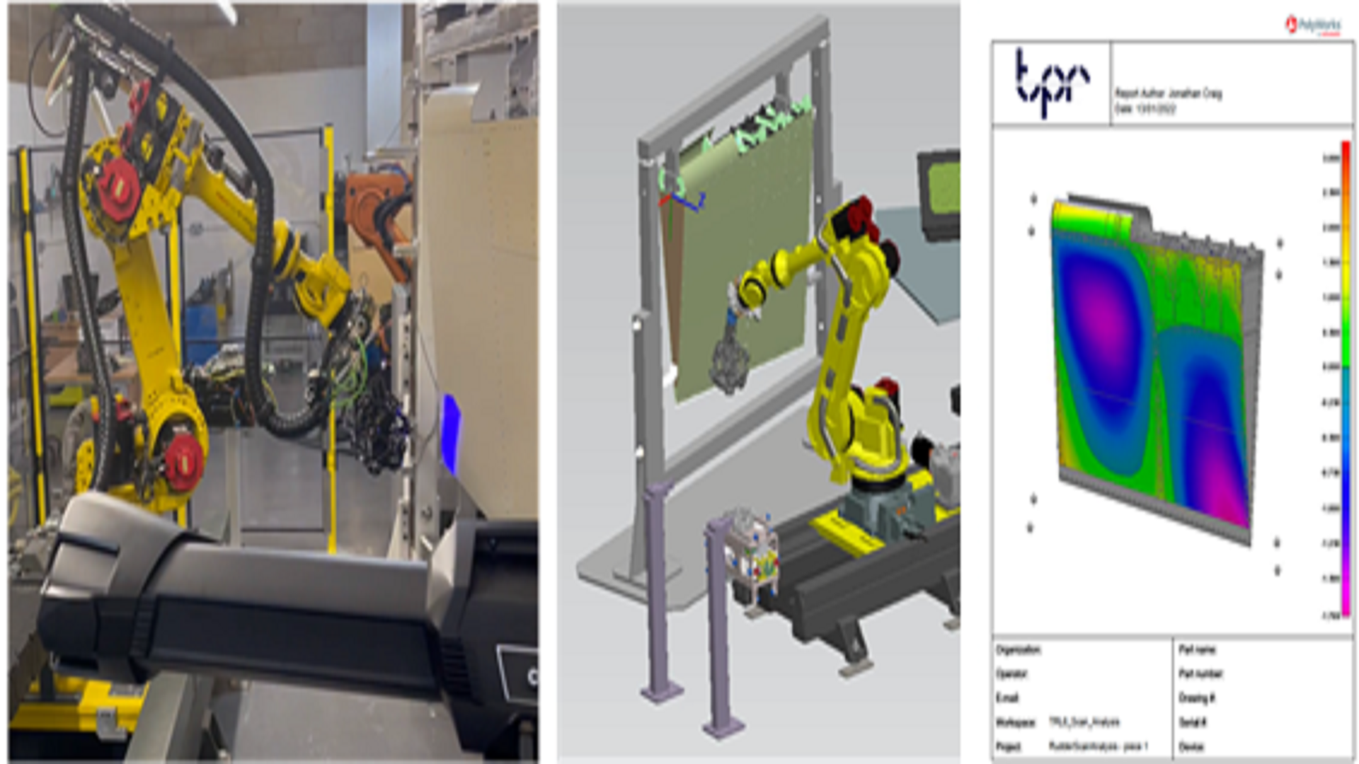
Fig 2.18 Data feedback on “form”
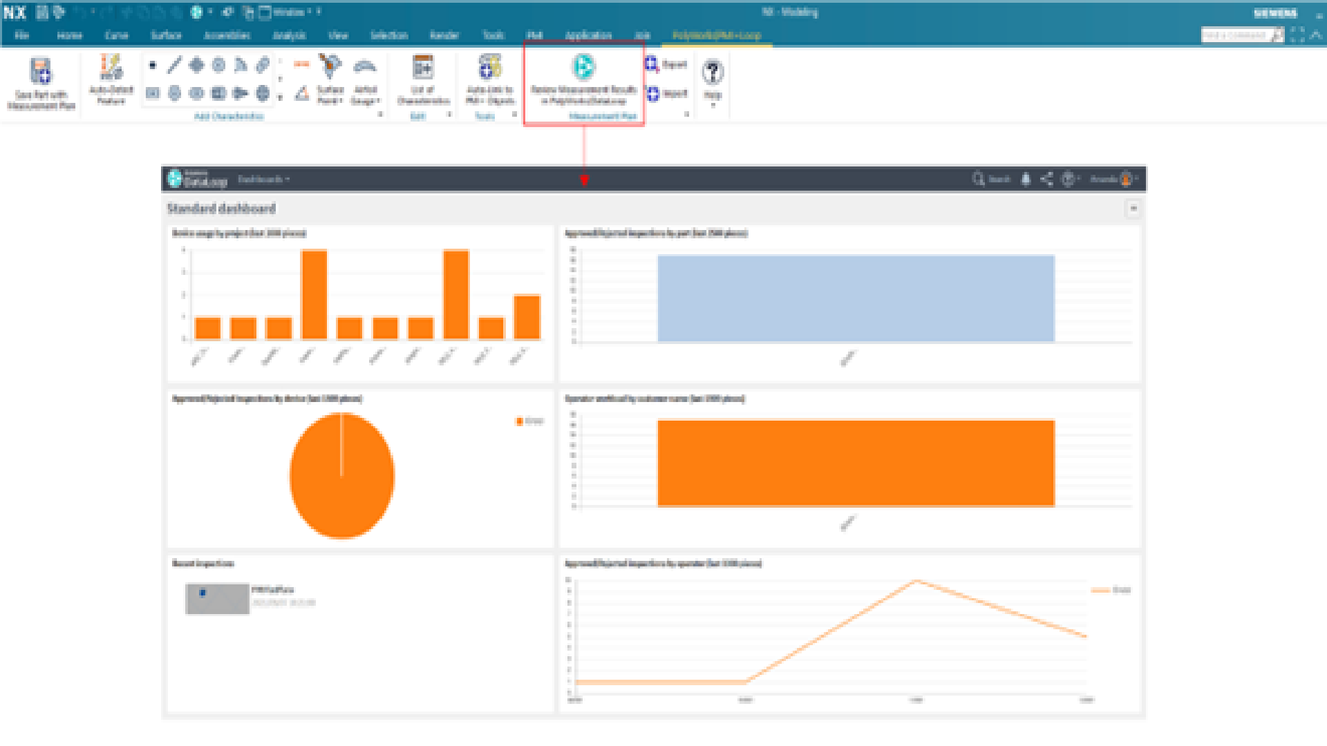
Fig 2.19 Real inspect metrics fed back to the designer
2.A.4 Discussion
The process demonstrated using the full Digital Thread, finding new productivity tools, and avoiding duplication of work and potential errors. A Cost Benefit Analysis was conducted on countersink drilling and inspection, as demonstrated vs original budget of manual data input, post OLP text editing and on-line commissioning on the 200 holes processed. That saving was £80k; which is more than the cost of either the laser scanner or drill. There are knowledge gaps in the supply chain, but this process – fully implemented – can lead to major productivity gains. Some assumptions, like the jig being the master are quashed – at least for this assembly.
2.B.1 Drill
TPR has been on a long journey in hole drilling. Initially with “no clamp-up” (driven by access through tooling), then requiring a clamp for hole quality (after experience noise on retract cycle), through straight pneumatic, to pneumatic with force feedback, to electro-mechanical with Force feedback.
The later phases of development centre around the impact of pressure on robot compliance
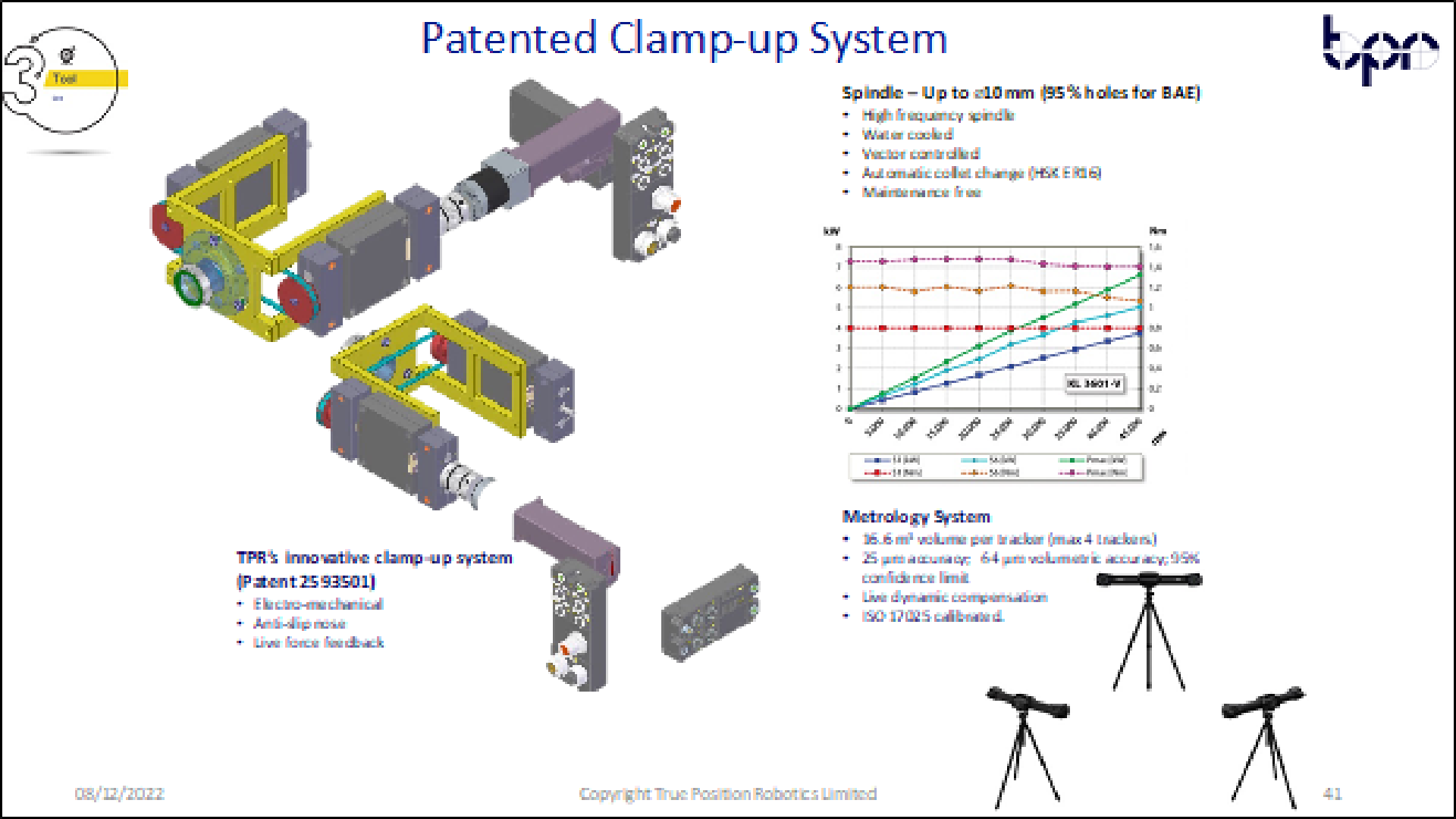
Fig 2.20 Drill Design
The latest design was tested on ADI and achieved TRL 6. The clamping system is modular and scalable – to fit on any drill. This was successfully tested on this project, using a FANUC drill approx. twice the size of TPR drill.
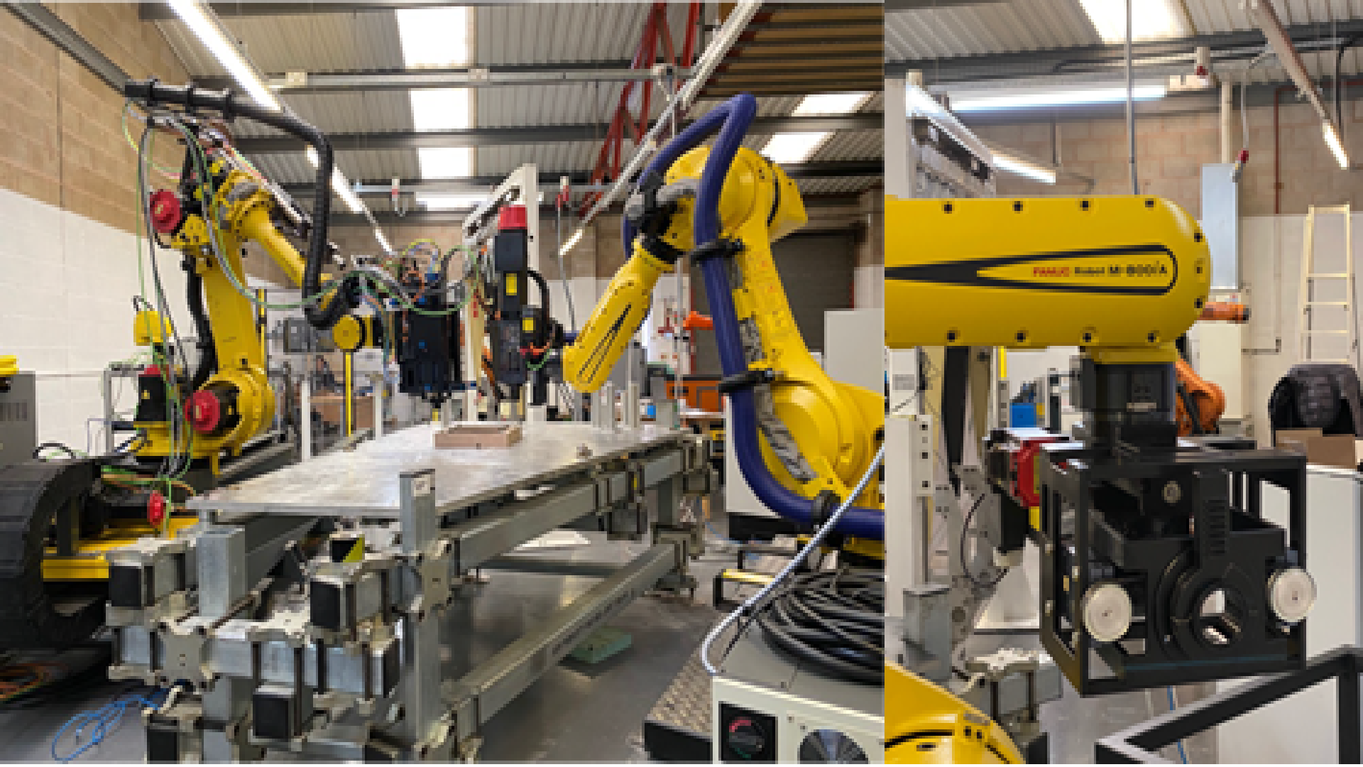
Fig 2.21 TPR drill compared to FANUC drill – both using TPR clamping system
For the clamping system, a special anti-skid nose is used – to stop tool skidding during the clamp-up phase.
All the clamp servo control system is managed on-the-drill, where the only external connections are power and data – leading to very simple tool change.
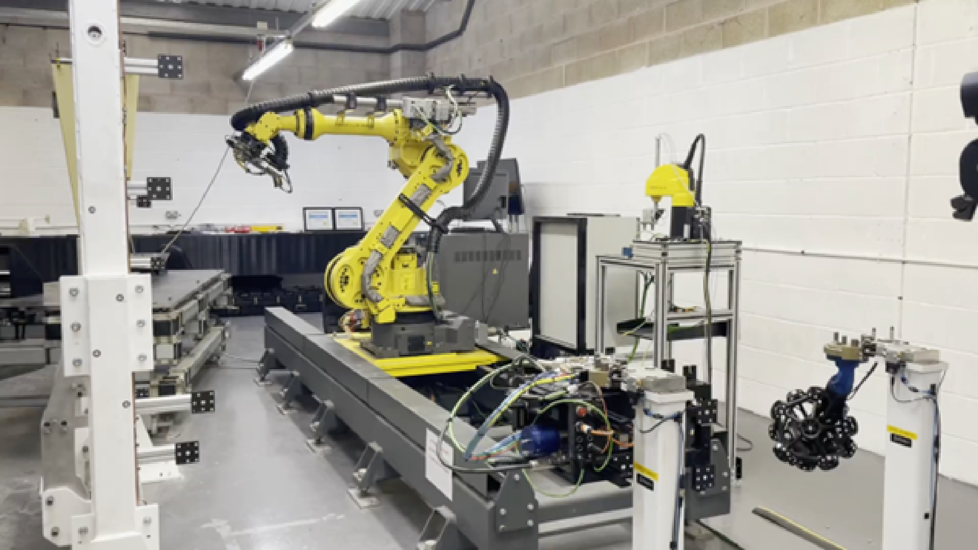
Fig 2.22 Tool change integration
The spindle size was selected for the bulk of market (customer led) – although from FANUC trials clearly larger spindles can be used.
Why electro-mechanical rather than pneumatic? The main reason is to achieve a countersink depth control that is even more challenging than true position. And this is on a surface that’s designed to move based on component thickness variation and flushness rules. So even with robot guidance there is a variable distance between tool and assembly. This method allows a controlled clamp-up over a range. On the assembly processed we recorded an average clamp-up distance of 3mm (starting in the air). But the “range” was double.
The advantage of a pneumatic clamp is it can be set to give an absolute dimension from the nose to the spindle. The disadvantages though are many. Firstly, the engagement is normally “quick” and tends to skid the robot tool on the surface. The second is trying to maintain a balance of clamping force, whilst not compromising the compliance of the robot. For the compliance, the industry has tended to use very large (high stiffness) robots, to minimise any compliance affects in the arm. So, mitigating the risk, by picking a machine where that effect is less likely. But that energy needs to go somewhere, and if not manged through the robot there is an increased likelihood of skidding.
TPR did trials a few generations of drill previously. This used force feedback to check clamp force – but this was between the tool and the robot flange. We found it was too far away to influence the actual control loop. But to give a repeatable force, we found the offset between nose and product (prior to clamp-up) had to be closely controlled. From the experience from DT – its know that assumption cannot be made!
For this project there was the first invention of the clamp-up mechanism, as well as giving a controlled countersinking depth (mechanics designed for single micron resolution), and the drill used as a 6D touch probe for true position with respect to the base, machine learning was introduced.
As part of the machine commissioning, at least two dry cycles are run, where we populate an understanding of the compliance at each hole position. This is using the same Statistical Process Control used for recording true position. If the range is too high on two cycles, a third is run – but this is an evergreen process – the more drilled cycles run, the more the system learns.
Using this methodology, as well as robot guidance, a bias is applied based on predicted compliance. This yielded very good results (described shortly). This gives a managed way of deploying lower payload tools, on smaller robots, saving on price and consistent with NetZero objectives (halving the automation energy needs).
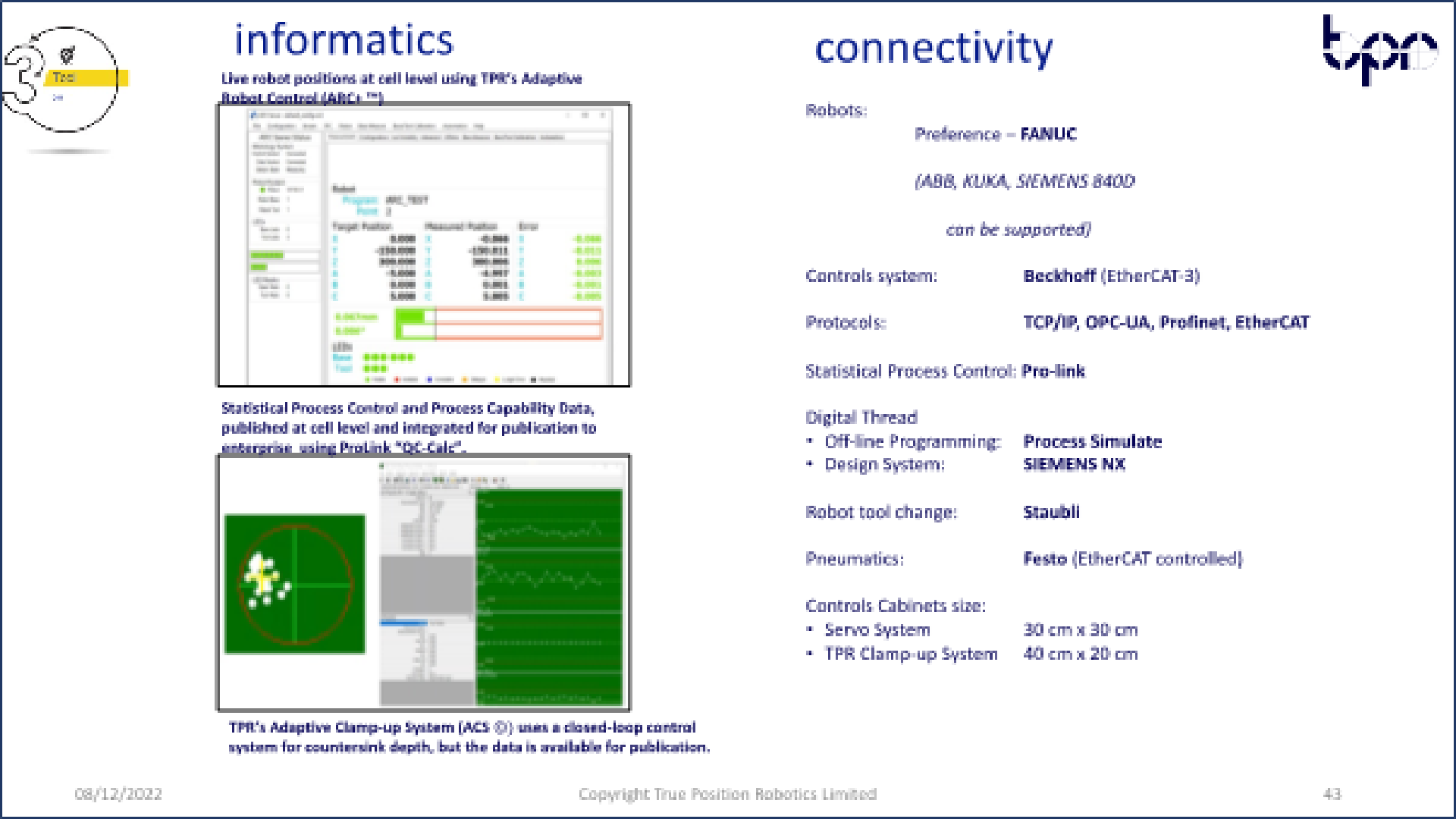
Fig 2.23 Informatics and connectivity
2.B.2 Results and Analysis
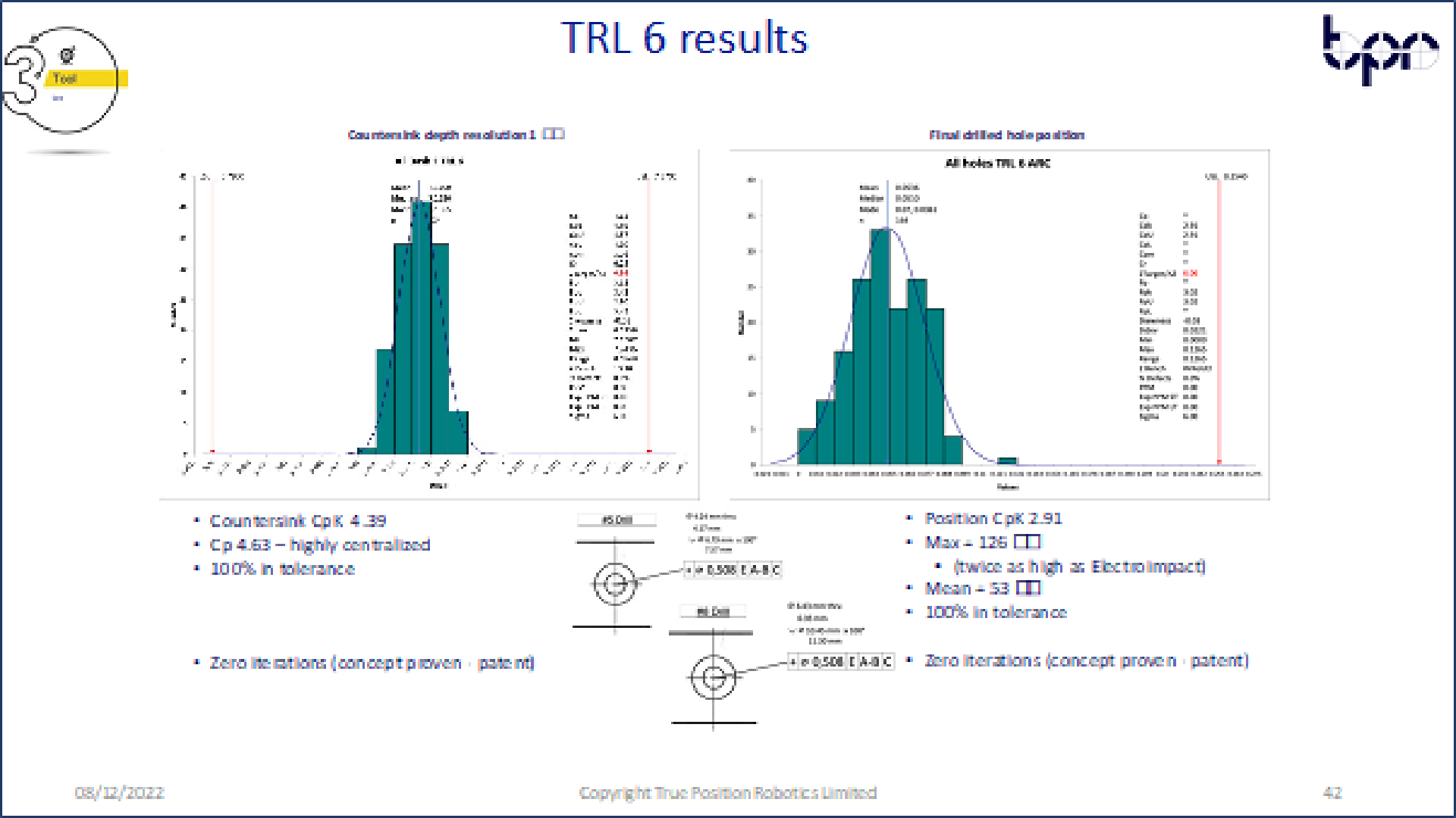
Fig 2.24 TRL 6 Results
For the countersink control, an extraordinary level of precision was achieved. Verified through a hole range of secondary measurement systems with touch probes, scanners, and callipers.
The control loop, of active force feedback on servo-controlled nose, giving offset to spindle rail gave 100% right first time, direct from DT. A calibration artefact was created and is now being automated for use in the cell – to ensure after collet change / drill bit change the correct offsets are held in the PLC.
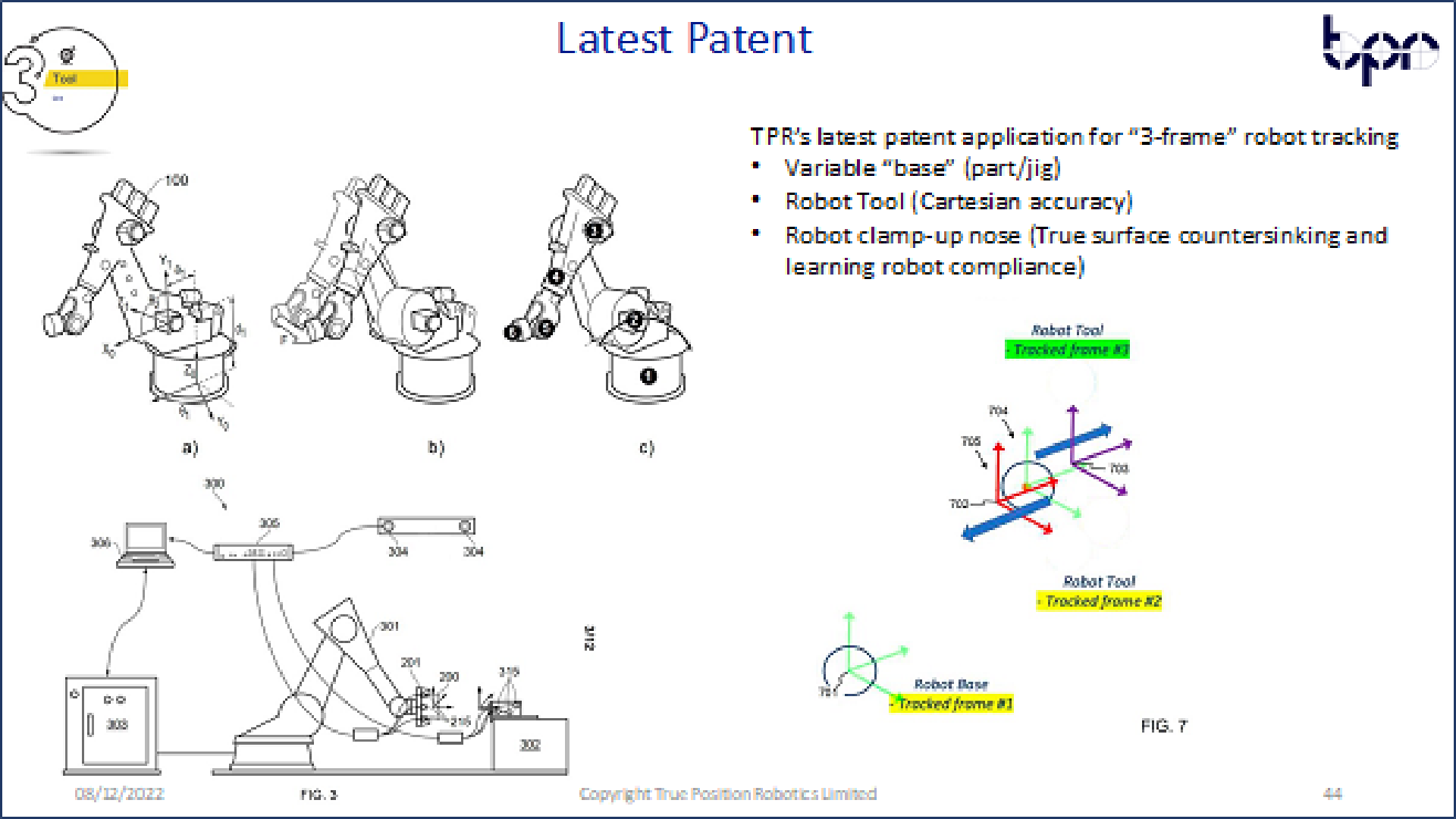
Fig 2.26 True Position
From earlier work in DT, a new process was developed where the BASE is a variable, and so the laser scanner becomes an active part of the drilling intelligence. But it was also found, where the target points are at large angles from the BASE, during clamp-up the body of the drill moves backwards due to compliance. So, the drill tool frame moves away from the product.
This is solved by introducing a third metrology 6D frame into the cycle, attached to the nose, simplifying true position reporting and machine learning (turning the bias into a 2D challenge).
We found this took robot accuracy from +/-0.2 mm (based on a +/-0.1 mm large volume metrology system 99.7% confidence limit); down to below +/-0.13 mm. Past experience informs us that some areas of the robot envelope have a lost motion of a similar number (+/-0.2 mm). This can lead to many iterations if using original robot guidance, compounded by movements in space of the drill body when clamping up at larger angles. This was observed in TRL 5 tests, where the coupons were mounted at 30° and 45° with respect to the table.
2.B.3 Discussion
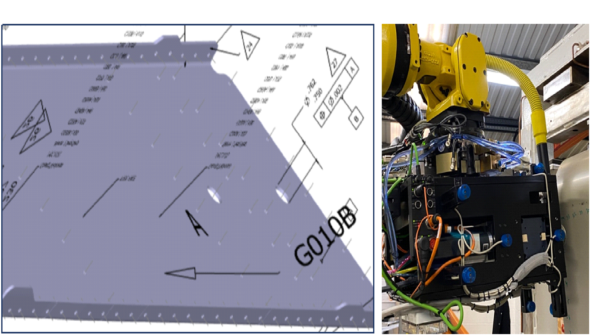
Fig 2.27 Respecting DT
Having a fuller understanding of the DT led to new thinking on robot drill deployment. The original drill concept was successfully demonstrated at TRL 6 for countersink control. But through the project, understanding the BASE is a variable introduces the laser scanner into the drill process – to find the parts and update robot BASES each cycle. So, it becomes an ADI solution not a separate drill solution.
The project started with robot metrology using active LED’s (NDI) and moved to Passive Markers (Creaform) as a consequence of NDI leaving the industrial market due to COVID. But the process and software’s support both types of large volume metrology solution. The requirements are based on a metrology capability of +/-0.1 mm 99.7% of multiple 6D frames (currently 3-off for drilling).
The use of both tools (drill and inspect), from an automation perspective – requires automatic tool changing which was successfully demonstrated, including data cables, fluids, pneumatics, spindle connections including servo and vector control, and dust extraction. TPR is currently engaged on a new research project inspired by IKEA
Currently with more than 1,000 fault free drilling and inspection tool change cycles this is designed (as with IKEA) to prove the quality of the solution, even with a large step reduction in price.
2.C Inspection
2.C.1 Laser Scanner
At the start of ADI, TPR had developed its own metrology integration solution using NDI’s optical CMM and instrumentation; and Nikon’s H120 laser scanner. The system was called AIR (Automated Inspection and Reporting) and the goal was to develop this to a production level. Unfortunately, NDI exited the market in 2020 due to COVID. This led to redefinition of the scope. Most metrology companies have their own scanner and tracker, so the first stage was to research comparable technologies – looking at high frequency measurements, large volume, system accuracy.
The NDI system has a maximum measurement frequency of 3500Hz, although this is based upon serial measurements of individual active LED’s. A more normal set-up of 20->30 markers would be measuring closer to 100Hz. Even though it wasn’t needed in this project, the natural frequencies of robots are 7->10Hz – so we didn’t want to go too low, and not be able to fully analyse robot performance.
For aerostructure assembly, up until the ADI project, we were always coached that (if using metrology) the systems had to cover the full volume of the complete assembly and track a master frame. What we found was the volume needs to cover a “part” with respect to a fixture, and the importance of multi-frame tracking has grown.
Finally, we were looking for system accuracy of 0.1 mm 99.7%. This (from experience) allows high accuracy robot guidance; but systems with lower accuracies create so many false directions (when guiding to +/-0.2 mm) it’s a key metric for successful implementation.
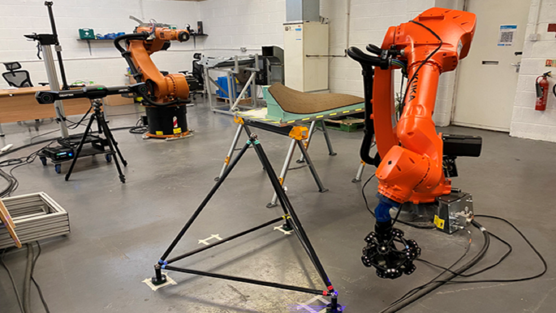
Fig 2.28 TPR’s AIR-2 System (Automated Inspection and Reporting), using Creaform technology
After a detailed market research, the solution selected was from Creaform. This (on paper) gave very similar performance levels to NDI. So, the first thing was to check that out.
Using the INORA tetrahedron gauging system, volumetric accuracy was checked. The gauge is based on 6 lengths of approximately 1m in length. The bars are calibrated to 1 micron with a measurement uncertainty of 8 microns.
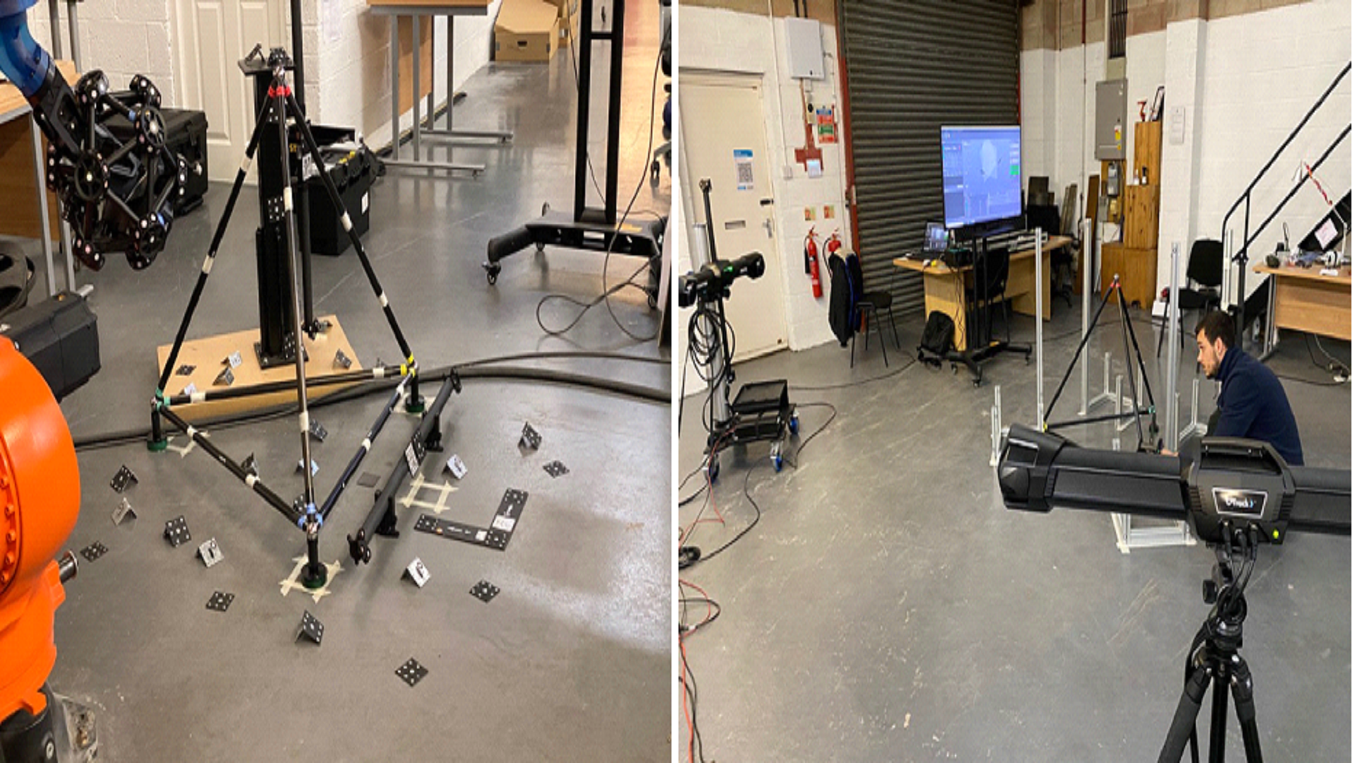
Fig 2.29 INORA tetrahedron tests for volumetric accuracy (robot and probing)
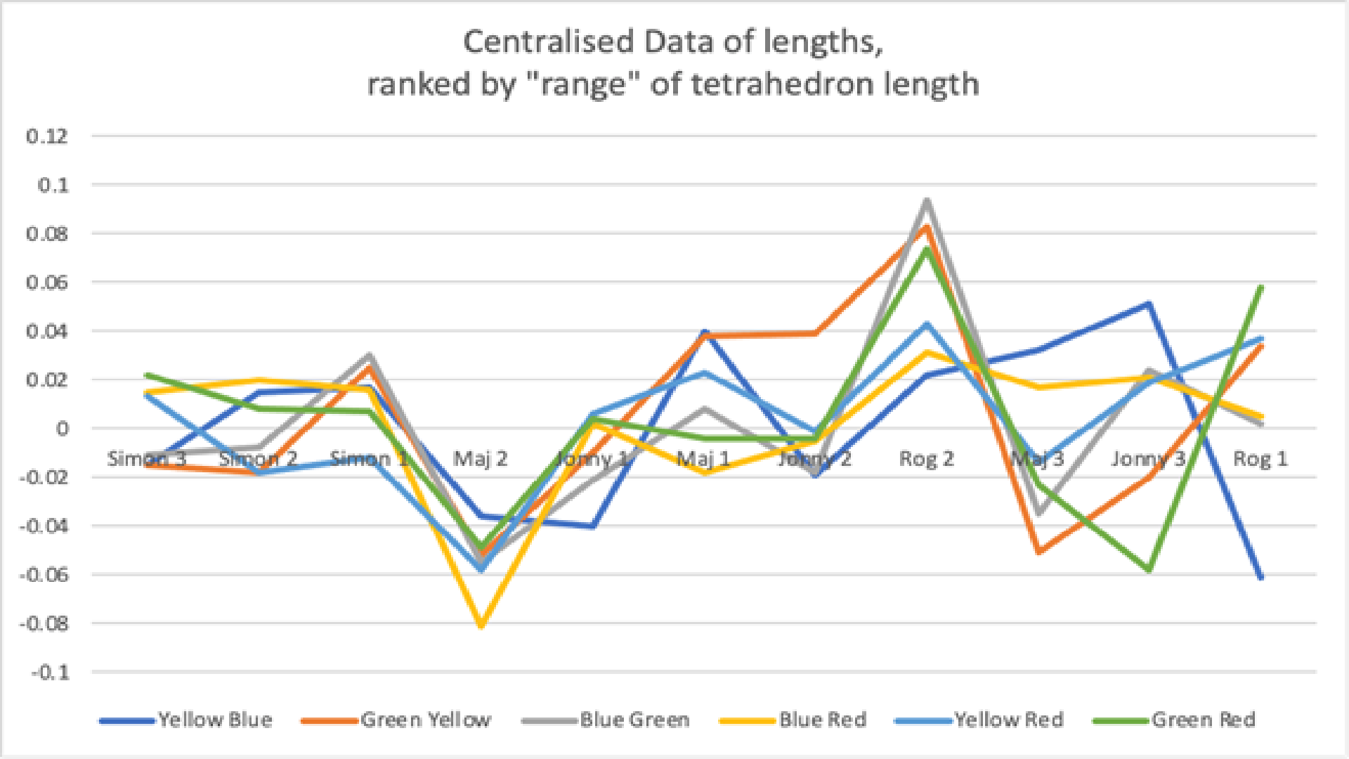
Fig 2.30 INORA tetrahedron tests for manual probing – multi-camera
It was found that operator skills had a key role in the accuracy / correlation between the bar lengths and the manual probed lengths. What was more frustrating was the best results were from two people with very different strategies!
It was found that operator skills had a key role in the accuracy / correlation between the bar lengths and the manual probed lengths. What was more frustrating was the best results were from two people with very different strategies!
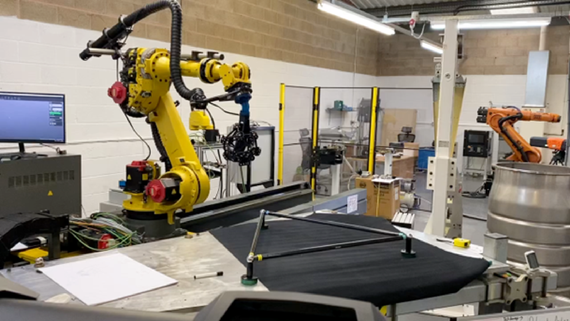
Fig 2.31 INORA tetrahedron tests for robot scanning
For robotics we went through three learning cycles, each increasing in-house knowledge and utilising new methods from AIR-1 that helped planning the robot paths and processes for probe qualification (the calibration of the laser scanner within the cradle). The project achieved range in length measurements of 20 microns and volumetric accuracy <100 microns confirming data sheet specifications. But it should be shared that set-ups and “best practice” are required to get to these numbers. Out-of-box its easy to miss those targets and training a key part of any successful deployments.
2.C.2 ADI system inspection toolkit
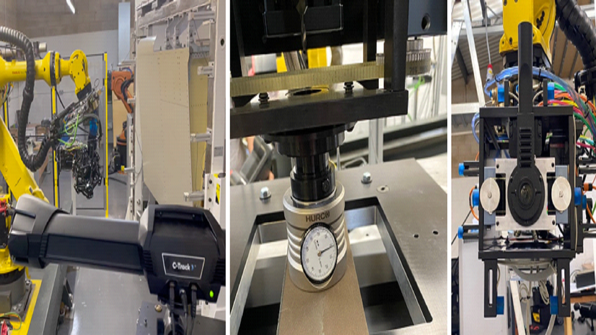
Fig 2.32 Inspection systems used on ADI
To complete the TRL 6 tests, the AIR-2 system (using Creaform hardware) was used for “Form” inspection and to find parts in fixture prior to claiming skin. TPR’s own calibration artefact was used to set drill bits and countersink settings – managed inside Beckhoff PLC. For ARC+ the NDI system was used for true position (superseded now by Creaform – delay was the very different instrumentation strategies).
Summary
The combination of hardware’s and software’s led to the successful completion of this project. This created the intelligence to allow a low payload robot, with simple drill tool to product the correct size countersunk holes at the right place, with an assembly in the correct shape, at an automation cost the partners can successfully adopt.
The use of multiple sensors increases the intelligence of the robot cell – making production effective and greener.
Conclusions
There are significant gaps in the support-side of the supply chain in the digital thread. Pursuing a full PLM implementation, however, appears to generate significant savings towards implementing robot automation. In this strategy described, the digital model is always the master and shop floor manual adjustment of the automation not allowed – the consequence of which would be to break the digital thread.
The goal was to successfully produce countersunk holes – in the right place, at the right depth, in the right shape, at a target price. All were achieved.
New knowledge gained in the assembly processes in aerostructures – leading the robot to treat the parts as unique (floating in a wider assembly); requiring a metrology system to find them in the fixtures at these very high tolerances. For this assembly, the jig is never the master.
The novel clamp-up system produced countersinks at a much higher quality than expected, with very high CpK. The drill instrumentation with ARC+ software manages robot compliance with no iterations needed in final assembly (TRL6 drill-off). The final innovation being to add in a third tracked frame into the software. Successfully managing true position control, even with high angular differences between target point, and BASE frame. Without it, if the target is aligned with the drill pre-clamp-up – once engaged the drill body moves back in space (due to robot compliance). This can lead to multiple iterations, reducing productivity.
Managing the assembly from a GD&T perspective makes engineering clearer, maximises PLM use, and simplifies deployment. Primarily by removing ambiguity.