Check the assembly
Use optical metrology to measure part positions in the fixture and inspect geometry at planned stages of manufacture.
Bring automated geometric measurement into your assembly process, from checking parts in the fixture to final validation.
TPR connects robots, optical metrology and analysis software to help you identify deviations earlier and make informed manufacturing decisions.
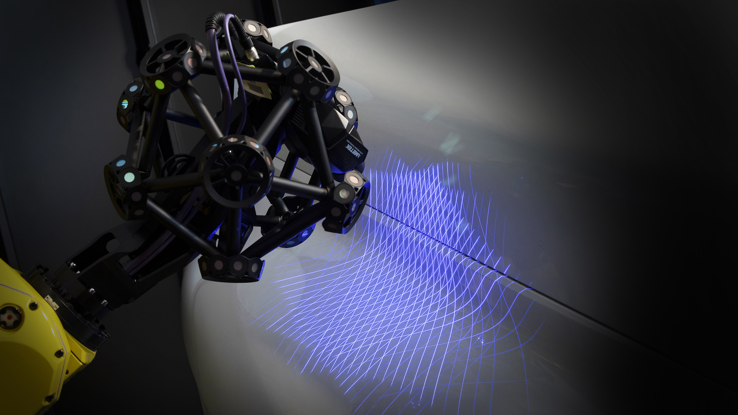
When inspection happens only at the end of assembly, a dimensional problem can mean costly rework. Integrating measurement into the build gives your team opportunities to check geometry before the next operation.
Use optical metrology to measure part positions in the fixture and inspect geometry at planned stages of manufacture.
Connect scanning hardware with analysis software and a measurement plan built around the features and tolerances that matter to your part.
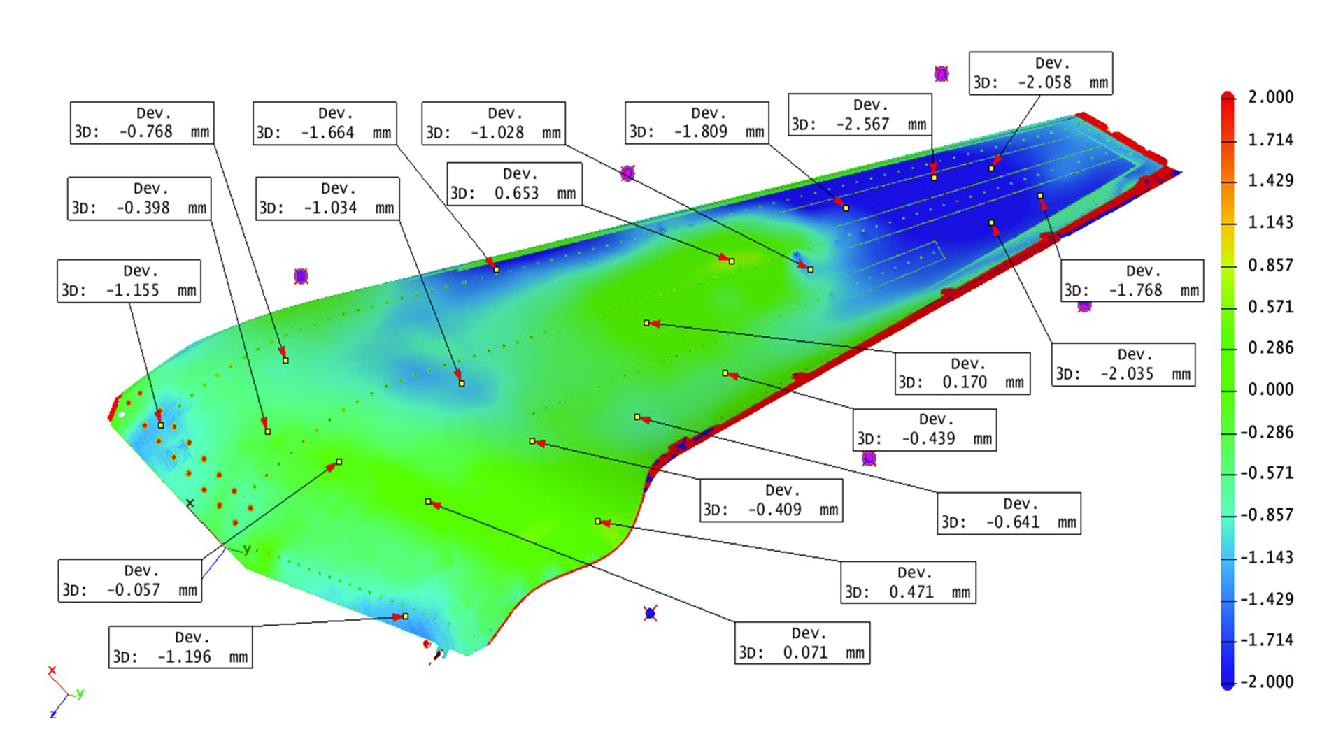
Use geometric inspection and reporting to support process decisions and final validation against your acceptance criteria.
TPR’s Robotic Software Hub connects the robot, metrology hardware and PC-based analysis software. It brings these elements together within the AIR inspection solution.
Connections are available for many industrial robot controllers. TPR can assess your existing equipment, interfaces and reporting requirements to define the integration.
Position the scanner for your measurement plan.
Capture the component’s geometry.
Turn measurement data into inspection results.
TPR’s published solution includes a full robotic tool-change option, allowing drilling and 3D inspection to share a robot where the application permits.
Systems can also be supplied as a complete turnkey solution, combining HMI, PLC and tooling with TPR’s network of specialist partners.
A starting point for your engineering review, based on TPR’s published inspection configuration.
| System software | TPR Robotic Software Hub for connecting the robot, metrology hardware and analysis software; AIR (Automated Inspection and Reporting). |
|---|---|
| Analysis software | PolyWorks Collaborative Suite. |
| Laser scanner | Creaform MetraSCAN-R BLACK Elite HD. Published scanning specification: 69 blue laser lines and 3 million points per second. |
| Optical tracker | Creaform C-Track Elite. Published measurement volume: up to 16.6 m³ per camera, with a maximum of four cameras per setup. Published volumetric accuracy: 0.078 mm at 95% confidence. |
| Connectivity | TCP/IP, OPC-UA, Profinet and EtherCAT. |
| Digital manufacturing | Smart templates for Siemens PLM integration, particularly Process Simulate robot simulation; offline robot programming support. |
| Robot & control options | Published options include FANUC robots/cobots, KUKA, ABB and Siemens 840D. Specific compatibility to be confirmed for your application. |
| Tool change | Option for full robotic tool change, including applications combining drilling and inspection. |
| System delivery | Turnkey integration with HMI, PLC and tooling through TPR and specialist partners. |
| Support services | Measurement plan creation, geometric dimensioning and tolerancing (GD&T) support, offline programming, training, maintenance and calibration. |
Published equipment values describe a particular configuration. Confirm scanner resolution, measurement uncertainty, operating volume and achievable cycle time against your parts and acceptance criteria with TPR.
Explore how optical metrology and Adaptive Robot Control support robot positioning alongside your inspection process.
Explore guided drilling and specialist tooling, then discuss the requirements for combining operations in one cell.
Yes. TPR’s approach covers measurements of parts in the fixture, inspection during the build and final geometric validation. The measurement plan defines which features to check and when.
The published solution includes robotic tool-change options for combining drilling and 3D inspection. Suitability depends on robot payload, reach, access, tooling and the required cycle time.
The Robotic Software Hub connects industrial robot controllers with PC-based processes. Share your controller, scanner, analysis software and interfaces so TPR can assess compatibility and integration work.
Start with part size and geometry, material and surface finish, features to inspect, tolerance requirements, cycle-time targets and how you need the results reported.
Tell us what you need to measure, when you need to measure it, and how the results will be used. We’ll help you explore the system and integration requirements.
For an initial enquiry, a short description is enough.